PICO MACOM INC. 12500 Foothill Blvd. • Lakeview Terrace, CA 91342 • (818) 897-0028 • (800) 421-6511 • FAX (818) 834-7197
3
Section 4
D E S C R I P T I O N S
A N T E N N A S E L E C T I O N
Pre-Amp
MPA-25
Broadband Single Channel
VHF
MX-7
0R
LOW
VHF
DSV-3
DSV-4
HIGH
HLSJ
20 dBmv to
Headend
10 dBmv
UV SJ
UHF
MX-4U
19 dBmv
DC-20
Test
-1 dBmv
18 dBmv
11 dBmv
12 dBmv
DC-20
Test
UHF
DSU-3
UVSJ
20 dBmv to
Headend
19 dBmv
-1 dBmv
18 dBmv
17 dBmv
12 dBmv
9 dBmv
10 dBmv
12 dBmv
The proper reception of Local
Off-Air Television Signals
(UHF-VHF) is essential to a quality
Private Cable system. The use of a
commercial quality off-air antenna
is a must for optimum television
reception. Since every location has
different needs and problems, a site
survey should be completed before
starting the system. There are three
methods of off-air reception; Broad-
band, Single Channel Yagi or a com-
bination of both. The method to use
will depend on the direction the
signals come from and the strength
of the signals. A good quality field
strength meter is a must for measur-
ing signals.
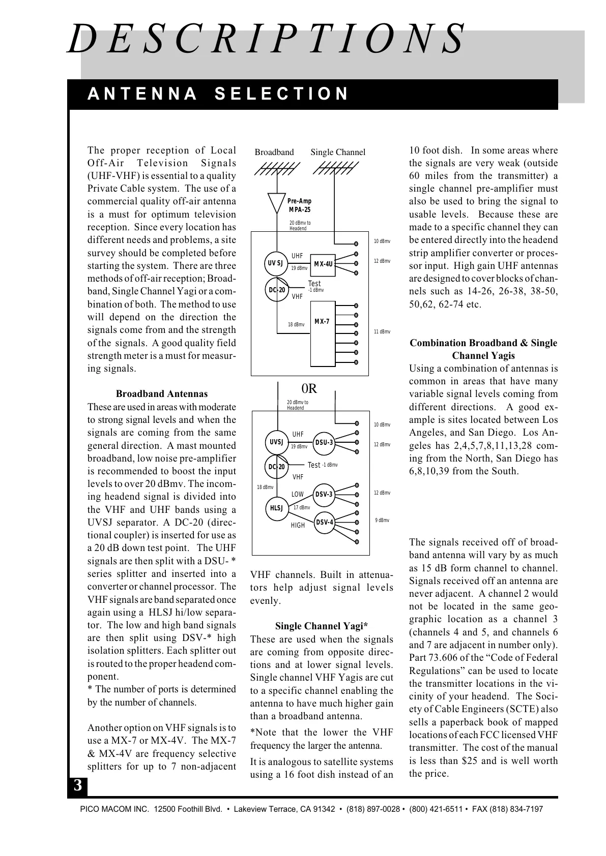
Broadband Antennas
These are used in areas with moderate
to strong signal levels and when the
signals are coming from the same
general direction. A mast mounted
broadband, low noise pre-amplifier
is recommended to boost the input
levels to over 20 dBmv. The incom-
ing headend signal is divided into
the VHF and UHF bands using a
UVSJ separator. A DC-20 (direc-
tional coupler) is inserted for use as
a 20 dB down test point. The UHF
signals are then split with a DSU- *
series splitter and inserted into a
converter or channel processor. The
VHF signals are band separated once
again using a HLSJ hi/low separa-
tor. The low and high band signals
are then split using DSV-* high
isolation splitters. Each splitter out
is routed to the proper headend com-
ponent.
* The number of ports is determined
by the number of channels.
Another option on VHF signals is to
use a MX-7 or MX-4V. The MX-7
& MX-4V are frequency selective
splitters for up to 7 non-adjacent
10 foot dish. In some areas where
the signals are very weak (outside
60 miles from the transmitter) a
single channel pre-amplifier must
also be used to bring the signal to
usable levels. Because these are
made to a specific channel they can
be entered directly into the headend
strip amplifier converter or proces-
sor input. High gain UHF antennas
are designed to cover blocks of chan-
nels such as 14-26, 26-38, 38-50,
50,62, 62-74 etc.
Combination Broadband & Single
Channel Yagis
Using a combination of antennas is
common in areas that have many
variable signal levels coming from
different directions. A good ex-
ample is sites located between Los
Angeles, and San Diego. Los An-
geles has 2,4,5,7,8,11,13,28 com-
ing from the North, San Diego has
6,8,10,39 from the South.
The signals received off of broad-
band antenna will vary by as much
as 15 dB form channel to channel.
Signals received off an antenna are
never adjacent. A channel 2 would
not be located in the same geo-
graphic location as a channel 3
(channels 4 and 5, and channels 6
and 7 are adjacent in number only).
Part 73.606 of the “Code of Federal
Regulations” can be used to locate
the transmitter locations in the vi-
cinity of your headend. The Soci-
ety of Cable Engineers (SCTE) also
sells a paperback book of mapped
locations of each FCC licensed VHF
transmitter. The cost of the manual
is less than $25 and is well worth
the price.
VHF channels. Built in attenua-
tors help adjust signal levels
evenly.
Single Channel Yagi*
These are used when the signals
are coming from opposite direc-
tions and at lower signal levels.
Single channel VHF Yagis are cut
to a specific channel enabling the
antenna to have much higher gain
than a broadband antenna.
*Note that the lower the VHF
frequency the larger the antenna.
It is analogous to satellite systems
using a 16 foot dish instead of an
 Loading...