PICO MACOM INC. 12500 Foothill Blvd. • Lakeview Terrace, CA 91342 • (818) 897-0028 (800) 421-6511 • FAX (818) 834-7197
4
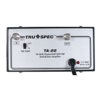
Front Panel
1. UHF or Combined: Connect UHF or
UHF/VHF antenna to this port.
2. VHF/FM:
Connect VHF antenna to this port
3. Separate or Combined:
If using separate VHF and UHF antennas, position
slide switch on "Separate". If using UHF/VHF broad-
band antenna, position slide switch on "Combined"
4. -10 dB:
Provides 10 dB attenuation to low-band input.
5. FM Trap:
Provides blocking of FM signal if required.
6. Gain Adjust:
Potentiometer provides for R.F. low-band
gain adjustment
7. Tilt:
Potentiometer provides for low-band slope adjustment
8. -10 dB:
Provides 10 dB attenuation to hi-band input.
9. -10 dB:
Provides 10 dB attenuation to uhf-band input.
F E A T U R E S
10. Gain Adjust:
Potentiometer provides for R.F. hi-band gain adjustment
11. Gain Adjust:
Potentiometer provides for R.F. uhf-band gain adjustment
12. Tilt:
Potentiometer provides for hi-band slope adjustment
13. UHF/VHF Output:
Connect this port to distribution system
14. Monitor -20 dB:
Used to monitor output signal
15. Power LED:
Indicates when amplifier is on.
16. Fuse:
Replace with 1 amp 250 volt fuse.
17. On/Off:
Power on or off switch
18. Power Cable:
The three prong type power plug connects to a 120 Vac,
60 Hz electrical outlet.
-10DB IN
FM TRAP
0DB OUT
-10DB
0DB
ATTENUATOR
-10DB
0DB
ATTENUATOR
GAIN
INPUT
VHF/FM
SEPARATE
COMBINED
UHF OR
COMBINED
GAIN
GAIN TILT
TILT
LO BAND
HI BAND
UHF
UHF/VHF OUTPUT
MONITOR-20DB
•
™
®
pec
u
UHF/VHF/FM
DISTRIBUTION AMPLIFIER
MODEL TA-52
CAUTION
DO NOT REMOVE SCREWS
FUSE
PL 1A ON
117V
40W
4 5 6 731
2
8
10 12119
13
14
15 16 17 18