Product information12
Copyright © 2012-2013 Pico Technology Limited. All rights reserved.ps3000ab.en r5
4.2.2
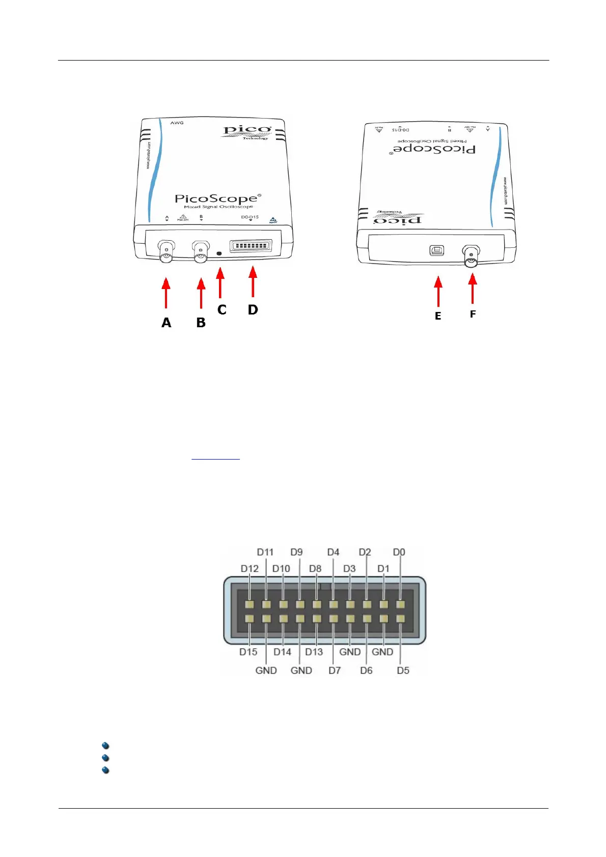
PicoScope 3000 Series MSOs
A. Input channel A
B. Input channel B
C. LED: shows when the oscilloscope is sampling data
D. Digital inputs D0-D15 (see below for further detail)
E. USB port. See Section 3 for guidance on USB connections.
F. AWG output
Digital input connection (D)
The digital input pins of the 20-pin IDC header plug are shown below. The diagram is
drawn as you look at the front panel of the device.
Precautions when connecting digital inputs
To avoid crosstalk on the digital inputs when probing signals with very fast edges,
please take extra care with the leads in the digital input cable:
Keep any leads carrying fast signals separated from the other leads.
Keep the leads carrying fast signals as close as possible to the ground leads.
Connect all four black ground leads to the ground of the circuit under test.
 Loading...