PicoScope 3000 Series A/B Oscilloscope & MSO User's Guide 11
Copyright © 2012-2013 Pico Technology Limited. All rights reserved. ps3000ab.en r5
4.2
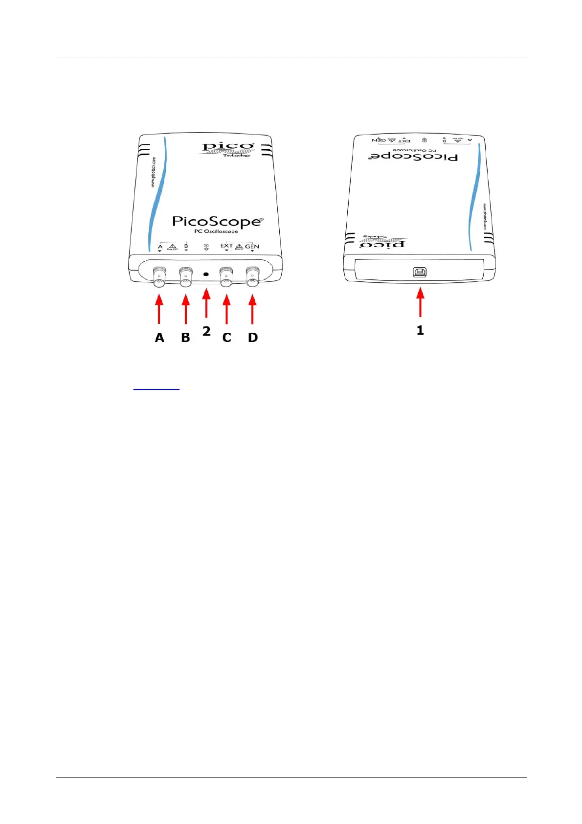
Connector Diagrams
4.2.1
PicoScope 3000 A and B Series 2-channel oscilloscopes
1. USB port. For best results, use the high-quality USB 2.0 or USB 3.0 cable supplied.
See Section 3 for guidance on USB connections.
2. LED: flashes red when the oscilloscope is sampling data.
A. Input channel A
B. Input channel B
C. External trigger input
D. Signal generator output
 Loading...