JP1 controls the least significant bit of the address, and JP3 the most significant bit.
Power jumper
JP4 selects whether the PiFace™ Relay+’s relays and any connected EXTRA board share the
same power source as the Raspberry Pi®. This supply can be either provided through the
Raspberry Pi®’s MicroUSB connector, or from an external supply provided through the Relay+’s
power screw terminals. With the jumper connected, the Raspberry Pi and Relay+ boards will
share a single power supply. Disconnected, they will each need to be powered separately.
Never have separate power supplies for both the Raspberry Pi® and Relay+, when the
jumper is connected.
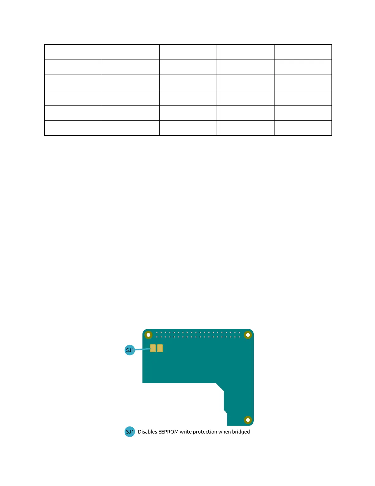
EEPROM jumper
The EEPROM on Relay+ allows the device to be detected, and for automatic software
configuration in accordance with the Raspberry Pi®’s HAT specification. The Raspberry Pi have
currently not finalised this specification yet.
The solder jumper SJ1 (located on the underside of the board) controls the write protection for
the EEPROM chip. By default this jumper is not bridged and the chip is write protected. To
reprogram the EEPROM bridge this jumper to disable the write protection.
 Loading...