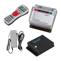
Analogue programming with PIKO Switch Control Box #55262
Procedure of programming:
1. Touch the programming button and release again. The programming LED will shine permanently and the decoder is in programming mode now.
2. Touch one of the red buttons on the Switch Control Box. That will be "servo address 1 to 4". The decoder will conrm the "address" with a short
shivering of the servo machine.
3. Setup the rst stop position with [+] or [-] buttons
4. Conrm the rst stop position with "OK"
5. Now setup the second stop position with [+] and [-]
6. As next you can setup the turning speed / setting time. After conrming the second stop position the decoder will permanently move the servo
machine between the two stop positions. With [+] and [-] you can setup the speed then.
7. After setting the speed conrm with "OK" and the programming is nished. The entered values are stored permanently now. To setup the other
servos repeat steps 1 to 7 with another red button at the beginning.
CV-schedule (Conguration Variables) of PIKO Switch Decoder for Servo Machines
Conguration of the Decoder
CV Description Value Range Factory Default
112 Software version (the processor used can be updated) - varies
113 Manufacturer code - 85
119 Decoder Conguration
Bit 0=0 Power Output 1 only on during servo movement
Bit 0=1 Power Output 1 always
Bit 1=0 Power Output 2 only on during servo movement
Bit 1=1 Power Output 2 always
Bit 2=0 Power Output 3 only on during servo movement
Bit 2=1 Power Output 3 always
Bit 3=0 Power Output 4 only on during servo movement
Bit 3=1 Power Output 4 always
Value
0
1 *
0
2 *
0
4 *
0
8 *
0-15 15
* denotes the factory default value
Conguration of the Servo outputs
CVs for Servo outputs
Description
Value
Range
Factory Defaults
1 2 3 4 1 2 3 4
120 130 140 150 1. Address High-Byte 0-6 0 0 0 0
121 131 141 151 1. Address Low-Byte 0-255 1* 2* 3* 4*
122 132 142 152 Stop position “red” Address 1 0-127 30 30 30 30
123 133 143 153 Stop position “red” Address 1 0-127 95 95 95 95
124 134 144 154 Setting time / Turning time 0-255 50 50 50 50
* When a Motorola center is used the factory programmed addresses are not usable and must be adjusted by the user via key programming.
Technical note: Below a minimal turning speed the servo machine may show effects of jerky movement. To avoid that just setup a higher /
faster turning speed.
Warranty Statement
Each component is tested for its complete functionality before distribution. If a fault should arise within the guarantee period of 2 years, we will repair the component free
of Charge upon production of proof of purchase. The warranty claim is void if the damage was caused by inappropriate treatment.
Please note that, according to EMV regulation the component may only be installed in vehicles which carry the CE logo.
All brand names mentioned are registered trademarks of the respective companies.
* Märklin is a trade mark of Gebr. Märklin & Cie. GmbH, Göppingen
** Motorola is a trade mark of Motorola Inc. Tempe-Phoenix (Arizona/USA)
55274-90-7001_2017
PIKO Spielwaren GmbH
Lutherstr. 30
96515 Sonneberg
GERMANY
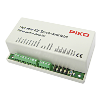
#55274 PIKO Switch Decoder
for Servo Machines
For connecting up to 4 PIKO Under Table Switch Machines #55272
Properties
• for Märklin* and DCC digital command stations
• switchable like a magnetic article decoder
• addresses for each servo machine freely choosable
• tunable stop positions
• tunable turning speed
• setup via solenoid controlling of the digital command station, via DCC-CV-programming or analogue with the help of the Switch
Control Box #55262
• power supply via track or separate power supply
• very low power consumption by the help of integrated switch mode voltage regulator
• servo-machine outputs with overload protection
Description
The PIKO Switch Decoder for Servo Machines is used to control common servo machines that are known from RC-model market for use on
model railroad layouts.
You can connect up to 4 pcs. PIKO Under Table Switch Machines # 55272 and control each one independently. The PIKO Switch Decoder for
Servo Machines acts like a switch decoder in digital systems and each servo machine can be assigned with it's own address. By the help of
the digital command signals the servo machine can then be moved into two different stopping positions. The PIKO Switch Decoder for Servo
Machines works in DCC and Motorola systems.
The stopping positions "red" and "green" can be setup independently from each other. Furthermore the turning speed between both positions
can be setup freely. With a simple solenoid-programming via the DCC or Motorola command station you can setup the address, the stopping
positions and the turning speed. When using a digital command station like PIKO Smart Control, that supports DCC-CV-programming, all
setups can be made via CV's, too.
Additionally an analogue programming and operation is possible in combination with PIKO Switch Control Box #55262.
Assembly of the PIKO Switch Decoder for Servo Machines
Connecting the PIKO Switch Decoder for Servo Machines
The connections "Gleis 1+2" (track 1+2) shall be connected with the track-outputs of the digital command station. In this case the PIKO
Switch Decoder for Servo Machines will be powered via the command station.
Notice: We recommend to connect a 16 V power supply to the contacts "Trafo 1 + 2".
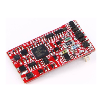
Connection of the servo machines to the PIKO Switch Decoder for Servo Machines
Each PIKO Switch Decoder for Servo Machines has four 3-pin connections for up to 4 servo machines.
The plugs of the servo machines should be plugged in with following alignment:
Data (white): towards frontside - power (5 V) center - mass (black) rearside inside housing)
Tipp: If the distance between PIKO Switch Decoder for Servo Machines and the servo Switch machine is too long you can nd extensions on
the after sales market (RC hobby).
Connect the PIKO Switch Control Box as following:
The programming in analogue mode is similar to digital
programming. Besides the two servo control buttons ("address")
there are two more buttons necessary to act as [+] and [-].
To make things simple the switch control box has a xed "logic" for
programming as following:
red
green
1 - 1 red
2 - 1 green
3 - 2 red
4 - 2 green
5 - 3 red
6 - 3 green
7 - 4 red
8 - 4 green
9 - common return
(RL)
A - trafo 1
B - trafo 2
C - track 1
D - track 2
S1 - Servo 1 + LED
S2 - Servo 1 + LED
S3 - Servo 1 + LED
S4 - Servo 1 + LED
PROG - prog-button + LED
123456789 A BCD S1 S2 S3 S4 PROG
Connections of the PIKO Switch Decoder
for Servo Machines
Connections / Descriptions at PIKO Switch
Control Box #55262
RL RL