Simple and extended function mapping
With simple function mapping, adjustable func-
tions like lighting, special function outputs, switching
(shunting) mode, and acceleration and braking can
be freely assigned to function keys F0 to F12 of the
DCC central control unit. For more information, refer
to the CV table at the end of this manual, as well as
the detailed user guide.
Smoke generator control
A smoke generator can be connected to outputs
A1 to A7 which are load-sensitive and react to the
model’s speed.
Electric coupler control
PIKO electric couplers are operated by tiny copper
wire resistance wires which heat up when the
decoder sends current through them. The heat
causes the wires to expand, causing the coupler
hook to move to the uncoupled position. The model
can then back away from the car. The model’s
decoder can be programmed to automatically shut
off current to the coupler mechanism after a certain
time period, without need to press another key.
Switching (shunting) scenario, remote coupling/
uncoupling
If your layout has remote electric uncouplers
installed, you can program the locomotive decoder
to perform a switching scenario like the following:
1) The locomotive runs in one direction for a certain
distance.
2) The locomotive stops and reverses direction.
3) The locomotive uncouples and moves back from
the uncoupled car for a certain distance.
4) The locomotive stops, and resumes switching.
For information on extended function mapping,
refer to the detailed operating instructions.
Servo control
The decoder can control up to four servo motors
via outputs. Further information can be found in the
detailed operating instructions.
Factory reset
CAUTION! When the decoder is reset, all factory
settings are erased! Only perform a reset if it is
absolutely necessary. If you nonetheless have
to reset the decoder remember that functions
programmed at the factory may no longer function
and you must reprogram the individual Function
Mapping (see FAQ)
To restore the decoder back to factory settings, use
CV8 for DCC programming and CV59 in Motorola
programming. To avoid having to re-enter all pro-
gramming after a reset, you can select beforehand
which areas of the decoder programming should be
reset to factory values. To restore the basic func-
tions of the decoder, enter a value of 1 in the Reset
CV (8 or 59). Information on extended reset can be
found in the detailed operating instructions.
Märklin and mfx
®
are registered trademarks of Gebr.
Märklin & Cie. GmbH, Göppingen Motorola is a reg-
istered trademark of Motorola Inc. Tempe, (Phoenix)
Arizona / USA RailCom
®
and RailComPlus
®
is a
registered trademark of Lenz Elektronik GmbH
Service:
Internet: www.piko.de
E-Mail:info@piko.de Hotline:
Tuesday + Thursday 16-18 Uhr
In the event of a defective decoder, please return
the decoder module to PIKO along with proof of pur-
chase, the decoder address, and a short description
of the problem.
Warranty Statement
Each decoder module is fully tested before
shipment. Nevertheless, should a malfunction occur
within the 2-year warranty period, we will repair the
module free of charge on presentation of the proof
of purchase. This warranty is voided if the unit has
been damaged by improper use. Please note that,
according to the German Electromagnetic Compat-
ibility Law (EMV Gesetz), the decoder module may
only be used inside models bearing the CE mark.
Product subject to changes. All rights reserved.
Printed 05/2019. Copy and duplication of this text
are permissible only with the permission of the
publisher.
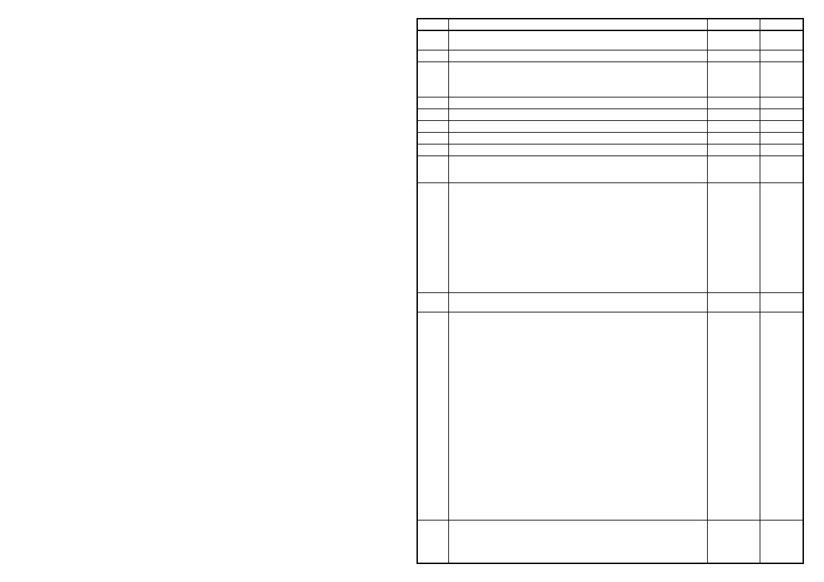
CV Description Area Value*
1 Locomotive address
DCC: 1 - 127
Motorola: 1 - 80
3
2 Minimum speed (the speed from 0 until the locomotive is running at speed step 1) 1 - 63 1
3
Acceleration delay
1 means every 5 milliseconds the actual motor speed is increased by 1. If the
maximum motor speed is 200 (CV 5 = 50 or CV 94 = 200), then the acceleration rate
from 0 to maximum speed is 1 second
0-255 25
4 Braking rate (time factor like CV 3) 0-255 6
5 Maximum speed (must be greater than CV 2) 1 - 63 45
6 Average speed (must be greater than CV 2 and less than CV 5) 1 - 63 13
7 Software version (The processor can be updated) - differently
8 Manufacturer identication decoder reset, values like CV 59
different
162
17
18
Long locomotive address
17 = higher value Byte
18 = lower value Byte
1 - 9999
192 - 231
0 - 255
2000
199
208
29
DCC standard conguration
Bit 0=0 Normal direction of travel
Bit 0=1 Opposite direction of travel
Bit 1=0 14 Speed steps
Bit 1=1 28 Speed steps
Bit 2=0 DCC-only mode
Bit 2=1 Automatic analog/digital recognition
Bit 3=0 RailCom
®
turned off
Bit 3=1 RailCom
®
turned on
Bit 4=0 Speed steps over CV 2, 5, and 6
Bit 4=1 Use the characteristic curve from CV 67 - 94
Bit 5=0 Short address (CV1)
Bit 5=1 Long address (CV 17/18)
0-63 14
30
Error codes for function outputs, motor, and temperature monitoring:
1 = fault function outputs, 2 = fault motor, 4 = overheating
0-7 0
33-46
Easy function mapping
Assignment of function outputs to CVs
CV 33 Lighting function key (F0) when moving forward
CV 34 Light function key (F0) when in reverse
CV 35 Function key F1
CV 36 Function key F2
CV 37 Function key F3
CV 38 Function key F4
CV 39 Function key F5
CV 40 Function key F6
CV 41 Function key F7
CV 42 Function key F8
CV 43 Function key F9
CV 44 Function key F10
CV 45 Function key F11
CV 46 Function key F12
Assignment of individual bits (with CV100 / 101 bit x = 0, standard)
Bit 0 Front light output
Bit 1 Rear light output
Bit 2 Function output A1
Bit 3 Function output A2
Bit 4 Function output A3
Bit 5 Function output A4
Bit 6 Switching (Shunting)
Bit 7 Acceleration / deceleration
0-255
1
2
4
8
16
32
64
128
1
2
4
8
16
32
64
128
0
0
0
0
0
0
59
Resetting to factory settings (also possible via CV8)
1 = CV 0 - 256, as well as CV257 - 512 (RailCom
®
Bank 7)
2 = CV 257 - 512 (RailCom Plus
®
Banks 5 & 6)
3 = CV 257 - 512 (extended function mapping banks 1 & 2)
4 = CV 257 - 512 (modulation function outputs banks 3 & 4)
0 - 4 0
 Loading...