14
NOTE: Detailed information on the PIKO
SmartDecoder 4.1 G is available as a PDF
le on our Webshop under the respective item
number. The le contains a full description of all
functions and operating possibilities for the new
SmartDecoder 4.1 G.
Description
The PIKO SmartDecoder 4.1 G decoder is a
powerful and compact multiprotocol decoder for G
scale locos, that can be used with standard DCC,
Selectrix, and Motorola digital systems as well as in
DC or AC analog mode. It automatically detects the
operating system in use.
This load regulated decoder operates on an 18.75
kHz frequency and are designed for standard DC
motors as well as bell-shaped armature motors (i.e.
Faulhaber, Maxon, Escap) that draw up to 1.2 A.
Temporarily higher current levels up to 2 A are easily
tolerated.
The decoder is both RailCom
®
and RailCom Plus
®
-
ready and recognizes ABC automatic stop sections
and ABC reduced speed sections.
The motor voltage can be controlled either by a
simple three-step motor speed curve, with minimum,
midpoint and maximum voltage settings, or by a
user-loadable speed curve, with 28 individually-set
speed steps.
The decoder provides two directional lighting
outputs, as well as seven additional special function
outputs. Slow-speed switching mode, with extended
slow-speed range, along with three accelleration and
braking rates, can be controlled via function keys.
Installing the PIKO SmartDecoder 4.1 G
The decoder may be mounted with the screws
provided.
Make sure that there is no short circuit caused by
the mounting screws. When you install the decoder,
make sure that there are no conductive connections
anywhere inside the vehicle.
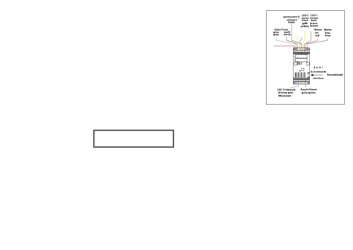
Connection of the PIKO SmartDecoder 4.1 G
Install the decoder carefully according to the
connection plan in this manual. Use an ohmmeter
to check whether the installation is correct. Check
for crossed wires and short circuits before and after
reinstalling the shell.
The decoder is protected against shorts and
overload. However, if during the installation cables
are reversed or if shorts occur between functions
(e.g. wheel set and motor), the protection will not
work anymore and the decoder will be damaged. We
disclaim all responsibility and guarantee in case of
misuse or damage of the decoder.
Place the model on your programming track with
programming mode activated on your DCC system.
During programming or when reading the model’s
DCC address, a small amount of current will ow
through the model, which does not affect the decod-
er; even in the event of a short circuit.
Special functions A1 bis A8
The special function outputs A1 to A8 of the decoder
are placed on the right screw terminal of the decoder
(Image 1). The power consumers connected to this
terminal will be provided with current by the U+
terminal. You can nd detailed information about all
connections in the detailed instruction manual.
SUSI interface
At the SUSI interface of the PIKO SmartDecoder
4.1 G you can either use a PIKO sound module with
SUSI or a suitable single-function decoder.
You can nd which CV should be programmed for
its respective function output in the operating instruc-
tions. The decoder is factory set to send data to the
PIKO sound module via the SUSI interface.
First-time use of the decoder (state of delivery)
Enter address 3 on your DCC control system.
Depending on your DCC system‘s data format, the
decoder will operate using 28 speed steps or in Mo-
torola mode. When using a RailCom Plus
®
-enabled
DCC system or with an mfx
®
-capable DCC system,
the decoder is recognized and can be operated
immediately. If the decoder is used on a conventional
analog layout, it can be controlled with a DC or AC
power pack. The decoder will automatically detect
the layout’s operating mode.
Note: In DC analog mode, your model will only start
at a higher voltage than what you may accustomed
to when operating analog models. You will need to
turn the throttle up for the model to start operating.
Function outputs in analog mode
It is possible to program the decoder so that function
keys F0 - F12 (as they are assigned in the function
mapping) can also be activated in analog mode.
To do this, CVs 13 & 14 must rst be programmed
with a DCC central control unit. The corresponding
values can be found in the CV table of the detailed
operating instructions. The light function F0 is
factory-set to “on.”
Motorola
The decoder has 3 Motorola addresses to activate
functions F1 - F12 on a Motorola-format DCC
system.
Conguration CVs
In addition to the decoder address, the indexed CVs
of a locomotive decoder are the most important
CVs. These are the CVs 29, 50 and 51 in the PIKO
SmartDecoder 4.1G. As a rule, an indexed CV
contains various basic settings of a decoder, such
as reversing the direction of travel. CV calculation
examples can be found in the detailed operating
instructions.
RailCom
®
, RailCom Plus
®
will be automatically recognized by a RailCom
Plus
®
-enabled DCC control system (i.e. PIKO Smart-
Control) and a locomotive icon, decoder name, and
its special function icons will appear on the control
system’s screen. With RailCom Plus
®
technology, no
locomotive data has to be stored in the DCC central
control unit and no locomotive addresses have to be
programmed into the decoder.
mfx
®
The PIKO SmartDecoder 4.1 G is specically made
for the mfx
®
data format. If your DCC control system
uses the mfx
®
format, then the decoder is automati-
cally recognized and is assigned its locomotive
symbol, decoder address, and its special function
symbols. With mfx
®
technology, no locomotive data
has to be stored in the DCC central control unit and
no locomotive addresses have to be programmed
into the decoder.
Braking
The decoder understands the following braking
methods:
• DCC braking function
• Märklin braking section (brakes with analog DC
voltage)
• ABC (Automatic Brake Control) braking section
The decoder can stop the model with two adjustable
braking distances that are accurate down to the
centimeter. More information on „braking behavior“
can be found in the detailed operating instructions.
Function outputs
A comprehensive description of all options related
to the function outputs can be found in the detailed
operating instructions.
PIKO SmartDecoder 4.1 G, Multiprotocol loco decoder for G scale locomotives
A short circuit in the area of the motor, lighting,
pick-up wiper, or wheelsets can destroy the
decoder and electronics of the model!
5HHG
.RQWDNW
JHOEEODX
\HOORZEOXH
5HHG
.RQWDNW
URW
UHG
 Loading...