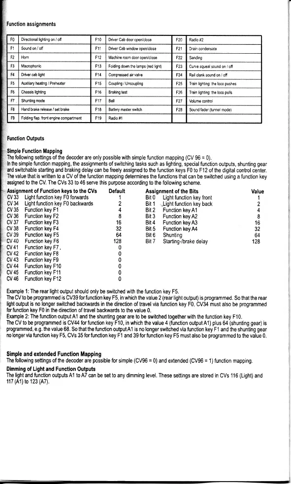
unction assignments
FO
Directional lighting
on / off
F10 Driver
Cab door open/close F20
Radio #2
F1 Sound on / off
F11 Driver Cab vnndow opentclose F21
Drain
condensate
F2
Horn
F12
Machine room
door
openlclose
F22
Sanding
F3
Mactophonic
F13
Folding
down the
lamps
(red
light)
F23
Curve
squeal
sound
on
/
off
F4
Ddver
cab
lighl
F14
Compressed
air
vafue
F24
Rail
clank sound on / ofi
F5
Auxiiiary heating /
Preheater
F15 Coupling /
Uncoupling F2s Train lighting:
the
loco
pushes
F6 Chassis
lighting
F16 Braking
test
F26
Train lighting:
the
loco
pulls
n, Shunting
mode F17
Bell
F27
Volume conkol
F8
Hand
brake
release / set
brake F1E Battery master switch
F28
Sound
fader
(tunnel
mode)
Ft)
Folding
flap,
front
engine
compartment
F19 Radio f1
Function 0utputs
Simple
Function Mapping
The following
settings
of
the
decoder are only
possible
with
simple function mapping
(CV
96
=
0).
ln the
simple function
mapping,
the assignments
of switching tasks
such as
lighting,
special
function
outputs,
shunting
1
and
switchable
starting and braking delay
can
be freely
assigned to
the
function keys
F0 to F12
of the digital
control cer
Ihe value
that
is wriften
to a CV
of
the
function
mapping
determines
the
functions
that
can be switched
using a function
assigned to the CV.
The
CVs 33
to 46
serve this
purpose
according
to the
following
scheme.
ksignment of
Function
keys
to the CVs Default
Assignment of
the
Bits
CV 33 Light function key F0 fonrards
1
Bit
0
Light
function
key
front
CV
34
Light
function
key F0
backwards
2 Bit 1
:,Light
function key back
CV 35 Function
key
F1
4 Bit
2
Function
key A1
CV
36 Function key F2
8 Bit
3
Function
keyM
;V
37
Function
key F3
16
Bit 4 Function
key A3
lV 38
Function
key
F4
32
Bit 5
Function
keyA4
)V
39
Function
key F5
64 Bit
6
Shunting
1
2
4
I
16
32
64
128
lV
40
Function key F6
128
Bit 7
StartingJbrake
delay
lV
41
Function key F7,
0
iV
42 Function key F8
0
]V 43 Function
key
F9
0
)V44
Function
key F10
0
]V
45 Function
key
F11
0
]V
46 Function
key F12
0
ixample
1: The rear light
output should only be switched with
the function key F5.
IheCVto
h
programmed
is
CV39
forfunction
key F5, in which
the
value
2(rear lightoutput)
is
programmed.
So thatthe
ight output
is no longer
switched backwards in the
direction of
travelvia function
key
F0,
CV34 must also be
program
'or
function
key F0 in the direction 0f travel
backwards to the
value 0.
ixample
2: The function
outputAl and the shunting
gear
are to be
s,vitched together with the function
key F10.
19
gear
center.
,ion
key
Value
I
ne uv ro
oe
Programmea
rs
uvJv
ror
runflon Key rc, rn wncn
rne
varue
z (rear rqnl
ouiput) ts
programmeq.
uo mat me
rear
light
output
is no longer
switched backwards in the
direction of
travelvia function
key
F0,
CV34 must also be
programmed
for
function
key F0 in the direction 0f travel
backwards to the
value 0.
Example
2: The function
output A1 and the shunting
gear
are to be
s,vitched together with the function
key F 1 0.
The
CV to
be
programmed
is
CV,l4
forfunction
key F10, in which the value 4
(function
outputAl)
plus
M
(shunting geafl
is
programmed,
e.g. the value
68. So
that the
function outputAl
is
no
longer
switched via
function key F1 and the
shunting
gear
no longer via
function key F5,
CVs 35
forfunction key
F1
and 39
for
function
key F5 must
also be
programmed
to
the
value
0.
Simple
and
extended
Function
Mapping
The following
settings of fre
decoder
are
possible
for
simple
(CV96
=
0)
and
extended
(CV96
=
1)
function
mapping.
Dimming of
Light
and
Function
Outputs
The
light
and function outputs
A1
to
A7
can be
set
to any dimming level. These
settings are stored in
CVs
116
(Light)
and
117
(A1)to
123
(A7).
 Loading...