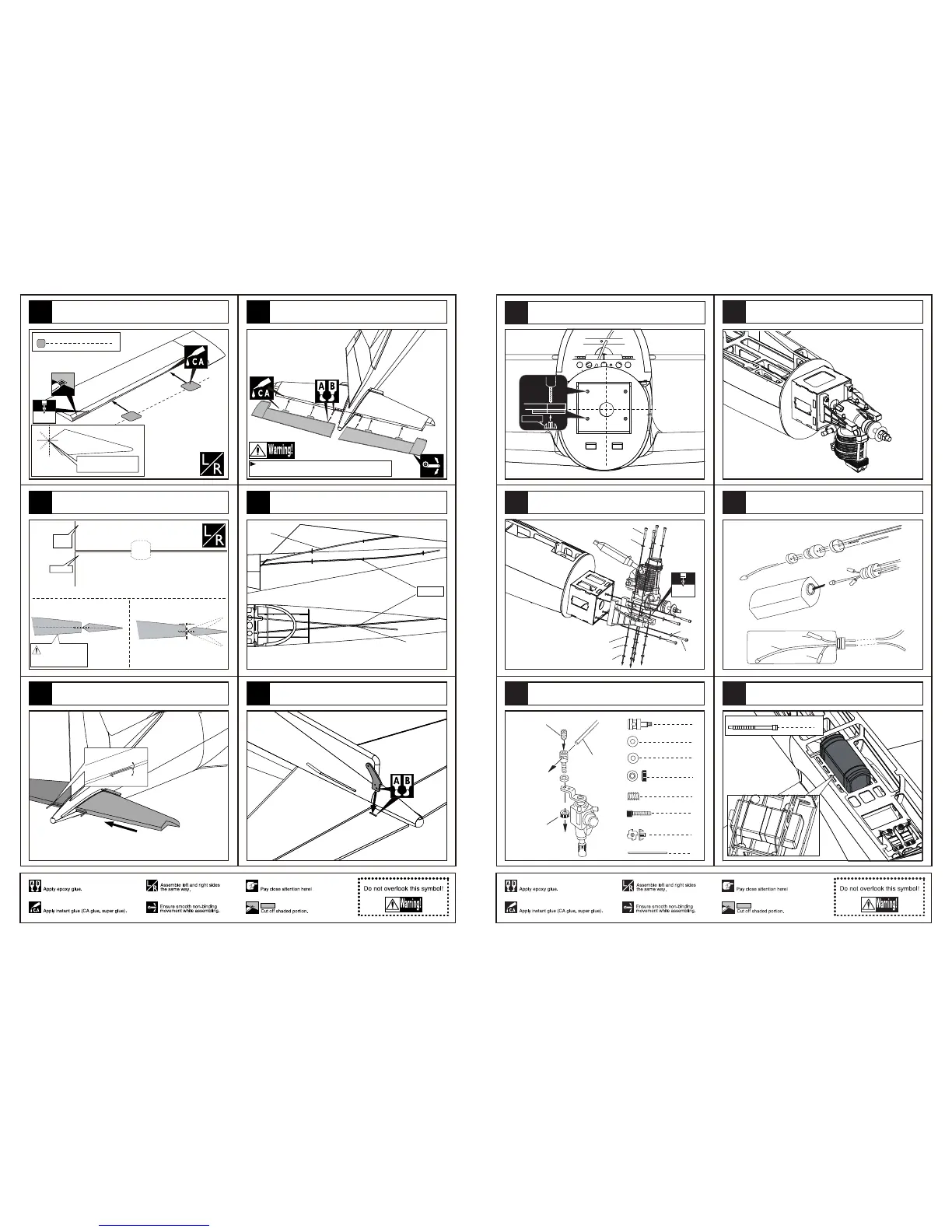
4
Pin hinge(24x24mm)
Make sure hinges are
mounted in the same line.
3mm
Apply instant type CA glue to the elevator and trim a
slot in appropriate position in the elevator as illustration.
Elevator
1mm
Trailing
edge
Make sure they are in
the right position while
installing.
Keep some space about 1mm width between the
elevator and horizontal tail edge.
Glue the stabilizer to to fuselage.
Securely glue together. If coming off during flights, you 'll
lose control of your airplane which leads to accidents!
Glue the elevator to the stabilizer by CA and epoxy.
The sketch map of the guide fiber tubes in the fuselage.
Glue the control horn to the slots in the elevator.
Elevator
Rudder
Side view
Top view
Rudder
4
21
20
19
16
18
17
5.2mm
Blind Nut
Set Screw (3x4mm)
Set Screw (2mm)
Rod (2x200mm)
Set Screw (2mm)
Washer (2mm)
Linkage Stopper
1
1
1
1
1
4
4
Washer (4x8mm)
4
Rod (2x400mm)
Blind Nut (4mm)
Screw (4x25mm)
Set Screw (3x4mm)
Assemble the throttle linkage.
Assemble the engine.
Drill four holes at the diameters as shown for engine mount.
Washer (4x8mm)
Washer (4x8mm)
Screw (4x35mm)
Screw (4x20mm)
Nut (4mm)
Spring Washer (4mm)
4mm
Washer (4x8mm)
Fuel supply line
Fuel spray line
Air pressure line
Assembly of the fuel tank.
The sketch map when the engine install completion.
Fix the fuel tank to appropriate position in the fuselage
with cable tie.
cable tie
2
9
48
47
46
44
45
43