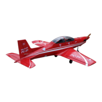
EasyManua.ls Logo

Pilatus PC - 21 User Manual

Pilatus PC - 21
8 pages
To Next Page IconTo Next Page
Page #1 background imageLoading...
Page #1 background image
PC - 21
Specification:
Length: 1624mm(64)
Wing span: 1397mm(55)
Wing area: 34.6sq.dm (3.72sq.ft)
Wing loading: 89.6g/sq.dm(29.4oz/sq.ft)
Flying weight: 3.1kg(6.8lbs)
Radio: 6ch & 6servos
Engine: 4-cycle 52-70
2-cycle 40-52
Motors: 4250 510KV
ESC: 60A
Battery: 6S 2200MAH 20C
Propeller: 14*7
SAFETY PRECAUTIONS
INSTRUCTION MANUAL
First-time builders should seek advice from people having building
experience.If misused or abused,it can cause serious bodily injury
and damage to property.
Fly only in open areas and preferably at a dedicated R/C flying site.
We suggest having a qualified instructor carefully inspect your
airplane before its first flight.Please carefully read and follow all
instructions included with this airplane,your radio control system
and any other components purchased separately.
(The people under 18 years old is forbidden from flying this model)
This R/C airplane is not a toy!
Centre of the Gravity.
Adjustment of the rudder, be sure it can work perfectly.
The side view once the model plane assemble completely.
Adjustment of the elevator,be sure it can work perfectly.
Adjustment of the aileron and flap,be sure they can work
perfectly.
25mm
25mm
AILERON
Side View
30mm
FLAP
AILERON AILERON
Right view
Side View
30mm
30mm
RUDDER
ELEVATOR
Side View
25mm
25mm
Top view
Position for
right diagram.
96mm
71
72
75
73
74
14
Question and Answer IconNeed help?

Do you have a question about the Pilatus PC - 21 and is the answer not in the manual?

Pilatus PC - 21 Specifications

General IconGeneral
BrandPilatus
ModelPC - 21
CategoryToy
LanguageEnglish

Summary

Aileron and Flap Adjustment

Rudder Adjustment

Elevator Adjustment

Center of Gravity (CG) Check

General Safety Precautions

Required for Operation

Tools Required

Before You Begin

Install Nose Landing Gear Servo

Assemble Nose Landing Gear to Front Gear Mount

Assemble Nose Landing Gear Servo to Fuselage

Fix Nose Landing Gear to Fuselage

Trim Cowling

Epoxy Exhaust to Cowling

Epoxy Cowling to Fuselage

Install Wheel to Fixed Landing Gear

Assemble Aileron to Main Wing

Install Aileron Servo

Install Nylon Control Horn and Linkage

Trim Cowling Shaded Line

Mount Receiver and Battery

Install Retract

Assemble Motor

Epoxy Interior Cockpit

Assemble Canopy

Mount Motor Mount Box

Assemble Aileron to Main Wing with CA Glue

Install Aileron Servo to Servo Mount

Install Control Horn and Linkage

Install Throttle Servo

Assemble Throttle Servo

Assemble Receiver and Battery

Assemble Retract

Drill Holes for Servo Extension Line

Mount Wings to Fuselage

Epoxy Belly Pants to Main Wing

Epoxy Main Wing

Apply CA Glue to Elevator and Trim Slot

Glue Elevator to Stabilizer

Drill Holes for Engine Mount

Assemble Engine

Assemble Fuel Tank

Sketch of Guide Fiber Tubes

Glue Control Horn to Elevator Slots

Assemble Throttle Linkage

Fix Fuel Tank

Assemble Steering Fullarm

Install Nose Gear Servo

Assemble Nose Gear Servo

Front View of Engine Installation

Side View of Engine Installation

Lock Linkage to Control Horn

Install Elevator Servo

Assemble Elevator Servo

Epoxy Fairing Sheet

Epoxy Vertical Fin

Apply CA Glue to Aileron and Pin Hinge

Epoxy Control Horns to Rudder Slots

Assemble Rudder Servo

Epoxy Fairing Parts to Fuselage

Assemble Nose Wheel

Install Nose Landing Gear

Keep Space Between Rudder and Tail Edge

Lock Linkage to Control Horn

Install Rudder Servo

Epoxy Rudder to Vertical Fin