Set Screw (3x4mm)
Set Screw (2mm)
Rod (2x650mm)
Set Screw (2mm)
Washer (2mm)
Linkage Stopper
1
1
1
1
1
Washer (4x8mm)
4
Rod (2x650mm)
Set Screw (3x4mm)
5.2mm
Blind Nut
Screw (4x35mm)
Screw (4x35mm)
Washer (4x8mm)
Spring Washer (4mm)
Nut (4mm)
4
Blind Nut (4mm)
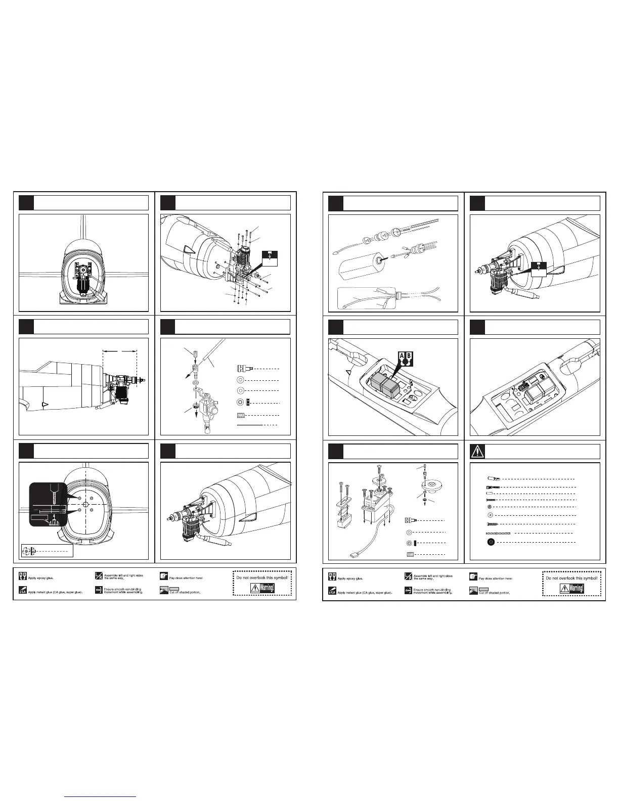
Assemble the throttle linkage.
Drill four holes at the diameters as shown for engine
mount.
Assemble the engine.
Washer (4x8mm)
Washer (4x8mm)
4mm
In case of 2-cycle & 4-cycle engine.
The front view of the engine install completion.
The side view when the engine install completion.
168 mm
The sketch map when the engine install completion.
8
41
40
37
39
42
38
Fuel supply line
Fuel spray line
Air pressure line
Epoxy the fuel tank in the fuselage.
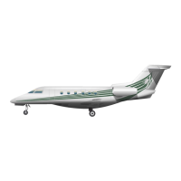
Assembly of the fuel tank.
Linkage Stopper
Washer (2mm)
Washer (2mm)
Nut (2mm)
Set screw (3x4mm)
Washer (
2mm
)
Set screw (3x4mm)
1
1
1
1
Install the switch and the throttle servo
Drill a small hole in appropriate position for throttle.
3mm
2
Steel wire (0.5x1500mm)
TP Screw (3x20mm)
4
1
Wheel (75 mm)
2
2
2
Clevis
Copper joiner
Aluminum tube(3x6mm)
2
2
Screw (2x10mm)
Nut (2mm )
2
Washer(2x5mm)
Assemble the throttle servo to the fuselage.
9
46
44
43
45
Accessory list for the coming installation steps.
47