EasyManua.ls Logo

Pilatus PC-9 User Manual

Pilatus PC-9
10 pages
To Next Page IconTo Next Page
Page #1 background imageLoading...
Page #1 background image
Pilatus PC-9
Specification:
Length: 1936mm(76)
Wing span: 2024mm(80)
Wing area: 64sq.dm(6.9sq.ft)
Wing loading: 106.3g/sq.dm(34.9oz/sq.ft)
Flying weight: 6.8kg(17.3bs)
Radio: 6ch & 8servos
Engine: 120 4-cycle
30cc gasoline engine
SAFETY PRECAUTIONS
INSTRUCTION MANUAL
First-time builders should seek advice from people having building
experience.If misused or abused,it can cause serious bodily injury
and damage to property.
Fly only in open areas and preferably at a dedicated R/C flying site.
We suggest having a qualified instructor carefully inspect your
airplane before its first flight.Please carefully read and follow all
instructions included with this airplane,your radio control system
and any other components purchased separately.
(The people under 18 years old is forbidden from flying this model)
This R/C airplane is not a toy!
Question and Answer IconNeed help?

Do you have a question about the Pilatus PC-9 and is the answer not in the manual?

Pilatus PC-9 Specifications

General IconGeneral
ManufacturerPilatus Aircraft
RoleTrainer aircraft
First Flight7 May 1984
Introduction1985
EnginePratt & Whitney Canada PT6A-62 turboprop
Maximum Speed593 km/h (368 mph, 320 kn)
Service Ceiling11, 580 m (38, 000 ft)
Number BuiltOver 250
Wingspan10.12 m (33 ft 2 in)
Height3.26 m (10 ft 8 in)
Max Takeoff Weight3, 200 kg (7, 055 lb)
Crew2 (student and instructor)
Primary UsersRoyal Australian Air Force, Swiss Air Force
Length10.18 m (33 ft 5 in)
Powerplant Output950 hp (710 kW)
Cruise Speed555 km/h (345 mph, 300 kn)
Rate of Climb20.9 m/s (4, 110 ft/min)

Summary

Specification

Safety Precautions

Before You Begin

Apply Epoxy Glue

Symbol indicating the use of epoxy glue for assembly.

Apply Instant Glue

Symbol indicating the use of instant glue (CA glue, super glue) for assembly.

Ensure Smooth Movement

Symbol ensuring smooth, non-binding movement during assembly.

Pay Close Attention

Symbol highlighting critical points requiring careful attention.

Step 1: Assemble Aileron to Main Wing

Step 4: Install Servo

Accessory List for Step 4

Lists parts required for installing the servo.

Control Surface Adjustments & CG

Rudder Adjustment

Ensuring the rudder operates perfectly for flight control.

Elevator Adjustment

Ensuring the elevator operates perfectly for flight control.

Center of Gravity (CG)

Determining and setting the correct center of gravity position.
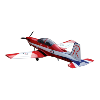
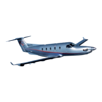
Related product manuals