This document provides the instruction and parts list for the Pilot K25/21 Vertical 3 Phase Reciprocating air compressor. It covers operation, safety, maintenance, component descriptions, and warranty information.
Function Description
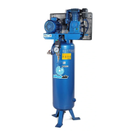
The Pilot K25/21 is a reciprocating air compressor designed to provide reliable and trouble-free compressed air. It is available in electric (240V & 415V) and petrol/diesel driven models. The unit automatically starts and stops based on factory-set cut-in and cut-out pressures, ensuring efficient operation and reduced wear.
Important Technical Specifications
- Model: K25
- Type: Vertical 3 Phase Reciprocating Air Compressor
- Maximum Pressure: 10 BAR (for "TM" or "K" series)
- Power Requirements (Electric Models):
- 240V & 415V
- Recommended wire sizes for 240V:
- 1.65 KW (2.25 HP): 1.5MM Square Wire (Max Length 20 M)
- 2.20 KW (3.00 HP): 1.5MM Square Wire (Max Length 10 M)
- Oil Type: PILOT PCO-40G (Stationary models) or PILOT PCO-30G (Portable models)
- Battery Wiring (Petrol powered units with electric start):
- Max. Cable length: 1.5 M, Cable size: 8 mm/sq
- Over 1.5 M length: Cable size of 15 mm/sq
Usage Features
- Automatic Operation: Electric models feature a pressure switch that automatically starts and stops the compressor when air receiver pressure drops below or reaches factory-set cut-in and cut-out pressures.
- ON/OFF Switch: Located on the pressure switch for electric units. Always switch the unit on and off via this switch to prevent starting against high pressure.
- Safety Valve: Equipped with a safety valve to release pressure in case of pressure switch cut-out failure.
- Overload Protection: Electric models include a manual overload protector to cut power to the motor in case of poor power conditions or motor over-temperature. A reset button is provided.
- Easy Start Valve (Petrol/Diesel Models): This valve should be opened for easy starting of the engine and closed for normal operation. It is located on the motor/pump platform (K25P, K30P) or in the discharge pipe from the pump to the air receiver (other models).
- Idle Down Feature (Petrol/Diesel Models): Designed to "idle down" to minimum operating speeds when cut-out pressures are reached, saving fuel and reducing wear.
- Pressure Gauge: Located on the air receiver, indicating pressure in PSI and KPA.
- Receiver Drain: Located at the underside of the air receiver for draining condensate.
- Oil Sight Glass: Located on the side of the compressor pump (opposite the flywheel) for checking the oil level.
Maintenance Features
- Fuses/Circuit Breakers: Check that they correspond to motor rating.
- Rotation Check (415-Volt Units): Verify rotation as indicated by the arrow attached to the unit.
- Extension Leads (240-Volt Units): Avoid using extension leads; if necessary, follow recommended wire sizes to prevent voltage drop and power loss.
- Oil Level: Maintain oil level at the center of the oil sight glass. Do not overfill.
- Oil Replacement: Replace oil every 1000 working hours or every six months. More frequent changes may be needed in humid or low duty cycle environments.
- Condensate Drainage: Condensation must be drained from the air receiver at least weekly.
- Crankcase Breather: Keep the unit clean, especially the crankcase breather, for proper cooling and breathing.
- Routine Maintenance: Should be performed at least every six months.
- Safety Precautions for Maintenance: Always isolate power and release all pressure from the receiver before attempting any maintenance.
- Transporting: Ensure all air is drained from the air receiver before transporting.
- Mounting: Do not bolt the compressor directly onto the floor. If bolting is necessary, use rubber vibration pads to leave a gap between the bolt head/nut and the compressor foot to avoid metal-to-metal contact and prevent cracks in the air receiver.
- Parts and Service: When requesting spare parts or service, always quote the model and serial number.
- Belt Guard/Pump Shroud: Never operate the unit without the factory-fitted belt guard (belt drive models) or pump shroud (direct drive models).
- Electrical Wiring: Never operate the unit with damaged or exposed electrical wiring.
- Modifications: Do not alter, adjust, or remove any components without technical support from Pilot Air or an authorized agent.