-1-
KLT500/KLR500
Installation Instructions
Инструкция по установке
Instrucciones de Instalación
הנקתה תוארוה
English, Русский, Español, תירבע
4-х проводной кабель шины BUS
Cable para el BUS de conexión
Teclado (sin cobertura posterior)
Bloque terminal de conexiones
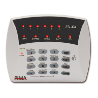
KLT500/KLR500 LCD Keypads
KLT500 and KLR500 are touch and silicon-rubber keys (respectively) graphic LCD keypads, designed for the FORCE Series intruder alarm
systems. The two keypads connect to the control panel over the bus. Up to 16 keypads can be connected to the FORCE.
The KLT500 and the KLR500 have a modern and sleek design that fits every indoor decoration.
The two keypads have four LEDs - Arm, Ready, AC, Alert/Fault - and a buzzer for various panel status indications.
The two keypads have settings for backlight, contrast, buzzer volume and ID no., and a tamper switch for detecting the opening of
the enclosure.
For complete information, see the FORCE’s Installation guide (P/N: 4410459).
Technical specifications
Screen size: 128X64 pixel
Voltage levels: 0, +12V
Operating Voltage Range: 9-14 VDC
Current Consumption: 50mA idle, 90mA max.
Sizes: 15 x 12 x 2cm
Weight: 235gr
CE compliance
Operating Temperature: -10°C to +55°C
Humidity (Max.): 93% R.H., Non-condensing.
Content of the product package
KLT500/KLR500 keypad + terminal block
How to install the KLT500/KLR500
Follow the next steps to connect the keypads.
1. Insert a slotted screwdriver to the notches on the keypad’s bottom, press gently and remove
the backplate.
2. Pass the BUS wires through the opening at the backplate.
3. Mount the backplate on a flat surface.
4. Connect the four BUS wires to the control panel: each wire connects between terminals with the same number on the keypad and
the control panel (1-1, 2-2, etc.).
5. Attach the keypad to the mounted backplate, top side first, and press until clicked.
Ordering Information
KLT500: P/N 8415010
KLR500: P/N 8415001