Do you have a question about the PIONEER DJ XDJ-700 and is the answer not in the manual?
Covers safety precautions, leakage current, and product safety notices for qualified technicians.
Guidelines for environmental protection, lead-free solder, and replacing parts.
Important notices regarding Flash ROM replacement and UTILITY settings backup.
Confirms firmware version, complaint resolution, interface, and product appearance after repair.
Lists necessary jigs for serial number writing and lubricants for maintenance.
Identifies the location of various PCB assemblies within the unit for service.
Shows the overall connection and signal flow between major assemblies of the unit.
Illustrates the signal paths and interconnections between key components.
Depicts the power distribution and voltage lines throughout the unit.
Details the step-by-step process the unit follows during power-on initialization.
Methods for diagnosing and resolving various operational issues, failures, and error codes.
Verifies PC communication via the USB B connector using Device Manager.
Checks the PC linkage status via the LINK connector using the unit's UTILITY menu.
Outlines the various service modes available for testing, diagnostics, and information display.
Confirms button inputs, LED indications, and LCD color patterns for proper function.
Details the procedure for measuring and adjusting the Jog dial's rotation load for optimal performance.
Displays version information, error history, and auto device diagnosis results.
Procedures for performing a factory reset and testing the auto standby mode.
Lists error codes, display words, contents, and notes for troubleshooting unit errors.
Explains alarm port pulse outputs for device detection and error indication during power-on.
Instructions for updating the device firmware using USB memory for Main and Panel CPUs.
Lists main components, their functions, part numbers, and references for service.
Step-by-step guide to safely remove the bottom cover of the unit.
Instructions for removing the display section, rear panel, and USBA assembly.
Steps to remove the shield case covering internal components for access.
Procedures for removing the main assembly and the TFT LCD screen.
Steps to disconnect and remove the PNLB assembly and associated components.
Detailed steps for removing the jog dial section and its associated assemblies.
Notes on firmware checks, updates, and necessary items after repair.
Procedure for writing the unit's serial number using PC software and USB connection.
Guide for inspecting and adjusting the Jog dial's rotation load for optimal performance.
Lists user-settable items and instructions for backing up/restoring settings via USB.
Lists parts included in the product packing and their corresponding part numbers.
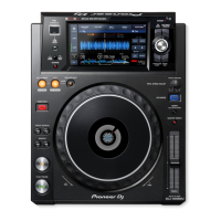
Details external parts of the unit, including screws, buttons, and covers.
Lists parts related to the display assembly, including the LCD and touch panel.
Lists all components associated with the Jog dial mechanism for identification.
| Brand | PIONEER DJ |
|---|---|
| Model | XDJ-700 |
| Category | Turntable |
| Language | English |