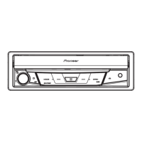
Do you have a question about the Pioneer AVH-X7700BT/XNUC and is the answer not in the manual?
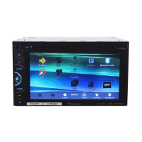
| Touchscreen | Yes |
|---|---|
| Bluetooth | Yes |
| USB Input | Yes |
| Preamp Voltage | 4V |
| Built-in Amplifier | Yes |
| Radio Tuner | AM/FM |
| Apple CarPlay | No |
| Android Auto | No |
| Navigation | No |
| HD Radio | No |
| EQ | 13-Band Graphic Equalizer |
| Resolution | 800 x 480 pixels |
| USB Ports | 1 |
| Audio Formats Supported | MP3, WMA, AAC, WAV, FLAC |
| Video Formats Supported | DivX, Xvid, MPEG-1, MPEG-2, MPEG-4, WMV |
| Preamp Outputs | 3 (Front, Rear, Subwoofer) |
| RMS Power Output | 14W x 4 |
| Peak Power Output | 50W x 4 |
| SiriusXM Ready | Yes |
| AUX Input | Rear |
Service manual intended for qualified technicians; avoid casual use.
Potential chemical exposure from California Proposition 65.
Exercise caution when checking laser diode emission.
Avoid opening covers; refer servicing to qualified personnel.
Guidelines for safe servicing, handling ICs, and power management.
Instructions for using lead-free solder and appropriate soldering techniques.
Details backup current consumption.
Lists supported media formats like DVD, CD, iPod, and Bluetooth.
Confirms customer complaint resolution and operational normalcy post-repair.
Identifies the physical layout of Printed Circuit Boards within the unit.
Lists necessary jigs, tools, and grease for specific service procedures.
Instructions for cleaning lenses and fans before product shipment.
Shows interconnections between major system blocks and units.
Illustrates the functional blocks and signal flow within the system.
Details the power supply configuration and voltage distribution.
Provides a step-by-step diagnostic guide for initial troubleshooting.
Flowchart for diagnosing issues specific to the DVD mechanism.
Detailed procedure for diagnosing and testing the pickup unit's performance.
Comprehensive list of error codes and their corresponding meanings.
Explains the purpose of each connector on the various units.
Describes the operation and mechanics of the FLAP system.
Addresses product overheat, speaker connection, or temperature issues.
Troubleshoots issues with Pandora, iPod, Bluetooth, and iTunes tagging.
Covers MirrorLink, USB, Disc, DivX, and format compatibility problems.
Guides on accessing and using the monitor test mode menu.
Procedures for adjusting EEPROM settings like flicker and backlight.
Steps to reset EEPROM settings to their factory defaults.
Tests for display signals: stripe, bar, RGB, raster, contrast, marker.
Tests rear video output signals: RGB, bar, ramp, raster, marker.
Procedures for testing DVD mechanism functions (FE, EDC, LD, CRG).
Procedure to verify touch panel responsiveness on the DVD mechanism.
Explains the purpose and implementation of the service test mode.
Details UART communication and key commands used in test modes.
Guidelines for safe handling of the mechanism to prevent damage.
Step-by-step instructions for safely removing the pickup unit.
Demonstrates proper and improper methods for handling the pickup unit.
Precautions and methods for adjusting the DVD unit's performance.
Method for verifying the PCL output signal frequency.
Exploded view illustrating the unit's packaging and included accessories.
Exploded view showing external parts and their assembly sequence.
Exploded view illustrating external components and their arrangement.
Illustrates specific points for grease application on external parts.
Details grease application on the gear assembly and related components.
Exploded view of the DVD mechanism module with part identification.
Schematic for mother unit with vehicle interface connections.
Schematic for mother unit's power supply for other components.
Schematic for mother unit's 2-channel DC/DC power conversion.
Schematic for mother unit's 1-channel DC/DC power conversion.
Schematic for mother unit's system communication control.
Schematic for Gerda unit, showing SDRAM and interfaces.
Schematic for AV Selector unit, detailing signal routing.
Schematic for OPAL unit, showing audio/video processing.
Schematic for mother unit's power IC section.
Schematic for mother unit's tuner power supply.
Schematic for mother unit's LVDS transmitter.
Schematic for mother unit's lithium battery charging.
Schematic for mother unit's USB power supply.
Schematic for mother unit's MS7.2 interface.
Schematic for mother unit's external interface.
Schematic for mother unit's Bluetooth module.
Schematic of monitor unit's PCB interface.
Schematic for monitor unit's LCD backlight driver.
Schematic for monitor unit's LCD power supply.
Schematic of monitor unit's LCD interface, COMDC block.
Schematic for monitor unit's LVDS receiver.
Schematic of DVD core unit, motor drivers, PU interface.
Schematics for Compound Unit A (Disc sensors) and Unit B (Clamp).
Schematic of keyboard unit, remote control interface.
Schematics for Main PCB and SW PCB units.
Displays essential waveforms for DVD/CD playback and operations.
PCB connection diagram for mother unit, showing component layout.
PCB connection diagram for monitor unit, Side B layout.
PCB connection diagram for DVD core unit.
PCB connection diagrams for Compound Units A and B.
PCB connection diagrams for keyboard unit (Side A & B).
PCB connection diagrams for Main PCB unit (Side A & B).
PCB connection diagrams for SW PCB unit (Side A & B).



 Loading...