Do you have a question about the Pioneer AVIC-F700BT/XS/UC and is the answer not in the manual?
| GPS Navigation | Yes |
|---|---|
| Bluetooth | Yes |
| USB Port | Yes |
| SD Card Slot | Yes |
| Touchscreen | Yes |
| iPod Compatibility | Yes |
| Display Size | 5.8 inches |
| Audio Formats Supported | MP3, WMA, AAC |
| Video Formats Supported | DivX, WMV |
| Steering Wheel Control | Yes |
General precautions for qualified service technicians.
Precautions for laser diode safety during servicing.
Warning about mercury content in LCD backlighting lamps.
Warning about chemicals in electrical parts known to cause cancer.
Details on laser diode wavelength and maximum output.
Caution regarding potential laser beam exposure during servicing.
Guidelines for safe repairs including parts, soldering, and environment.
Maintaining product performance through adjustments and characteristic confirmation.
Proper use of specified lubricants, adhesives, and replacement parts.
Procedures for cleaning optical pickups, lenses, and other parts.
Protecting products from damage during transit using shipping modes or screws.
General precautions for product handling, ICs, and pickup units.
Procedure to change the EJECT LOCK/UNLOCK status of the CD mechanism.
Notes on using lead-free solder and appropriate soldering iron temperatures.
Technical specifications for the AV Navigation Receiver.
Supported disc and content formats for media playback.
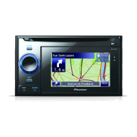
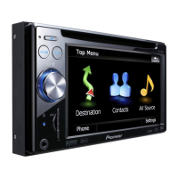
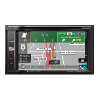
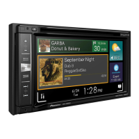
Identification and functions of the unit's panel buttons and controls.
Instructions for inserting and ejecting discs.
Instructions for inserting an SD memory card.
Instructions for ejecting an SD memory card.
Diagram showing external connections for the AV navigation system.
Check points to confirm product quality after servicing.
Location of main Printed Circuit Boards (PCBs) within the unit.
List of jigs, tools, and greases required for servicing.
Recommended cleaning tools and procedures for specific parts.
Diagram illustrating the overall system connections between major units.
Functional block diagram of the system, showing units and data flow.
Flowchart illustrating the system's operational sequence and signal timing.
List of error codes, their displayed messages, and potential causes.
Description of functions for each pin of the unit's connectors.
Troubleshooting flowchart for diagnosing common power and display issues.
Diagnosis for system wake-up and Navi image issues, checking power and signals.
Diagnosis for touch panel and hard key issues, checking signals between boards.
Diagnosis for audio or guide voice issues, checking audio output signals.
Procedures for entering and activating the Test Mode menu.
Description of available test items within the Test Mode menu.
Screens for Audio and GPS tests within the Test Mode.
Screens for NAND Flash memory and TMC error rate tests.
Screen for initiating graphics tests and selecting test items.
Screens for checking version info and testing/calibrating the touch panel.
Screens for testing unit ports and SD card functionality.
Screen for turning backlight on/off and adjusting brightness.
Cautions and procedures for adjusting the CD mechanism module.
Procedures for UBOOT and WINCE image upgrades using an SD card.
Procedures for using Test Disc 1, including MIC test.
Specification for Test Disc 2, used for user data deletion.
Procedure for removing the unit's outer case.
Procedure for removing the CD mechanism module.
Procedure for removing the monitor assembly.
Procedure for removing the Navi unit.
Procedure for removing the AV unit.
Procedures for removing the panel and keyboard units.
Procedure for removing the upper and lower frames of the mechanism unit.
Procedures for removing the CD core unit and the pickup unit.
Procedure to check grating angle after replacing the pickup unit.
Points for AV unit adjustment, showing PCB layouts.
Procedure for adjusting video level, specifying input signal, output, instruments, and specs.
Procedures for aging and flicker adjustment for screen display.
Exploded view and parts list for the product's packing contents.
Exploded view of the unit's exterior parts (Part 1).
Exploded view of the unit's exterior parts (Part 2).
Exploded view of the unit's exterior parts (Part 3), showing cable sets.
Exploded view of the CD mechanism module.
Schematic diagram of the AV Unit's Power Supply and IF sections.
Schematic diagram of the Keyboard Unit, showing button and connector functions.
Schematic diagram of the CD Core Unit, including pickup and driver circuits.
Schematic diagram of the AV Unit's Audio/Video sections.
Schematic diagram of the AV Unit's Tuner section.
Schematic diagram of the AV Unit's System uCOM section.
Schematic diagram of the AV Unit's RGB LED Driver section.
Schematic diagram of the AV Unit's IF section.
Schematic diagram of the CD Mechanism Module, showing switches and motors.
Waveforms for CD Core Unit signals, including various tests.
PCB connection diagram for the AV Unit, showing component placement.
PCB connection diagram for the Keyboard Unit (Side A).
PCB connection diagram for the Keyboard Unit (Side B).
PCB connection diagram for the CD Core Unit (Side A).
PCB connection diagram for the CD Core Unit (Side B).
List of miscellaneous electrical components including ICs and transistors.
List of resistors with their circuit symbols, part numbers, and locations.
List of capacitors with their circuit symbols, part numbers, and locations.
List of miscellaneous parts like diodes, switches, connectors, and inductors.