EasyManua.ls Logo

Pioneer CDX-FM657 User Manual

Pioneer CDX-FM657
64 pages
To Next Page IconTo Next Page
Page #1 background imageLoading...
Page #1 background image
PIONEER ELECTRONIC CORPORATION 4-1, Meguro 1-Chome, Meguro-ku, Tokyo 153-8654, Japan
PIONEER ELECTRONICS SERVICE INC. P.O.Box 1760, Long Beach, CA 90801-1760 U.S.A.
PIONEER ELECTRONIC [EUROPE] N.V. Haven 1087 Keetberglaan 1, 9120 Melsele, Belgium
PIONEER ELECTRONICS ASIACENTRE PTE.LTD. 253 Alexandra Road, #04-01, Singapore 159936
C PIONEER ELECTRONIC CORPORATION 1999
K-ZZY. FEB. 1999 Printed in Japan
ORDER NO.
CRT2316
UNIVERSAL MULTI-CD SYSTEM
CDX-FM657 X1N/UC
Service
Manual
CONTENTS
1. SAFETY INFORMATION ............................................3
2. EXPLODED VIEWS AND PARTS LIST.......................4
3. SCHEMATIC DIAGRAM ...........................................14
4. PCB CONNECTION DIAGRAM ................................26
5. ELECTRICAL PARTS LIST ........................................34
6. ADJUSTMENT..........................................................38
7. GENERAL INFORMATION .......................................45
7.1 PARTS .................................................................45
7.1.1 IC................................................................45
7.1.2 DISPLAY....................................................51
7.2 DIAGNOSIS ........................................................52
7.2.1 DISASSEMBLY .........................................52
7.2.2 TEST MODE..............................................54
7.3 BLOCK DIAGRAM ..............................................60
8. OPERATIONS AND SPECIFICATIONS.....................62
- See the separate manual CX-892(CRT2356) for the CD mechanism description, disassembly and circuit
description.
- The CD mechanism employed in this model is one of C7 series.
CDX-FM657/X1N/UC
CDX-FM657 X1N/EW
CDX-FM657 X1N/ES

Other manuals for Pioneer CDX-FM657

Question and Answer IconNeed help?

Do you have a question about the Pioneer CDX-FM657 and is the answer not in the manual?

Pioneer CDX-FM657 Specifications

General IconGeneral
BrandPioneer
ModelCDX-FM657
CategoryCD Player
LanguageEnglish

Summary

CD Player Service Precautions

1. SAFETY INFORMATION

1.1 CDX-FM657/X1N/UC

Safety cautions and warnings for the UC model.

1.2 CDX-FM657/X1N/EW

Safety precautions, laser product info, and diode specs for the EW model.

2. EXPLODED VIEWS AND PARTS LIST

2.1 PACKING

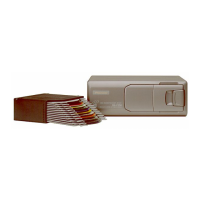
Exploded view and parts list for the packing configuration.

2.2 EXTERIOR

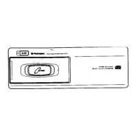
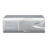
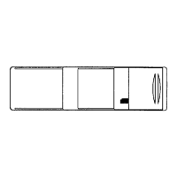
Exploded view and parts list for external components.

2.3 CD MECHANISM MODULE

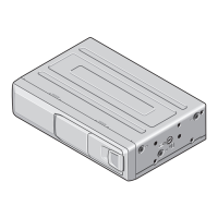
Exploded view and parts list for the CD mechanism module.

2.4 MAGAZINE ASSY

Exploded view and parts list for the magazine assembly.

3. SCHEMATIC DIAGRAM

3.1 OVERALL CONNECTION DIAGRAM

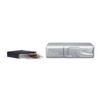
Overall connection diagram showing interconnections between major units.

3.2 EXTENSION PCB

Schematic diagram for the extension PCB.

3.3 ΑΝΤΕNNA SELECT UNIT

Schematic diagram for the antenna select unit.

3.4 DISPLAY ASSY

Schematic diagram for the display assembly.

Waveforms

4. PCB CONNECTION DIAGRAM

4.1 CD CORE UNIT

PCB connection diagram for the CD core unit.

4.2 EXTENSION UNIT

PCB connection diagram for the extension unit.

4.3 MECHANISM PCB

PCB connection diagram for the mechanism PCB.

4.4 SWITCH PCB

PCB connection diagram for the switch PCB.

4.5 MOTOR PCB

PCB connection diagram for the motor PCB.

4.6 ΑΝΤΕNNA SELECT UNIT

PCB connection diagram for the antenna select unit.

4.7 DISPLAY ASSY

PCB connection diagram for the display assembly.

5. ELECTRICAL PARTS LIST

6. ADJUSTMENT

6.1 MODULATOR ADJUSTMENT

Procedure for adjusting the modulator.

6.2 CHECKING THE GRATING

Procedure to check grating angle after pickup unit replacement.

6.3 ADJUSTMENT OF ELEVATION WHEN THE CD CORE UNIT HAS BEEN REMOVED FOR MAINTENANCE

Adjustment procedure for CD core unit elevation after removal or error.

7. GENERAL INFORMATION

7.1 PARTS

Lists and details of various parts used in the unit.

7.2 DIAGNOSIS

Information and procedures for diagnosing issues.

7.3 BLOCK DIAGRAM

Block diagram illustrating the system architecture and signal flow.

8. OPERATIONS AND SPECIFICATIONS

8.1 OPERATIONS

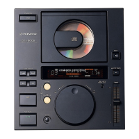
Instructions for operating the CD player and remote controller.

8.2 SPECIFICATIONS

Technical specifications of the CD player and its accessories.

Related product manuals