EasyManua.ls Logo

Pioneer DC-221Z User Manual

Pioneer DC-221Z
47 pages
To Next Page IconTo Next Page
Page #1 background imageLoading...
Page #1 background image
©
PIONEER
Service
CIRCUIT
DESCRIPTIONS
REPAIR
&
ADJUSTMENTS
aes
=
ORDER
NO.
Re
ARP-811-0
STEREO
DOUBLE
CASSETTE
TAPE
DECK
AMPLIFIER
C-2212
DC-2202
(Silver
Version
of
DC-2212Z)
e
DC-221Z
is
the
same
as
the
DC-220Z
except
for
the
exterior
design
(color).
e
Models
DC-221Z
and
DC-220Z
come
in
seven
versions
distinguished
as
follows:
Applicable
model
DC-221Z
DC-2202
fe)
AC120V
only
U.S.A
Power
requirement
Destination
Oo
AC220V
(240V)*
European
continent
ae
AC240V
(220V)*
United
Kingdom
AC110V/120V/220V/240V
(Switchable)
General
market
AC240V
(220V)*
Australia
AC220V
(240V)*
West
Germany
AC120V
only
Canada
*Change
the
primary
wiring
of
the
power
transformer.
This
service
manual
is
applicable
to
the
KU,
HB,
HE,
S
and
YP
types.
For
servicing
of
the
HEZ
type,
please
refer
to
the
additional
service
manual
(ARP-812).
For
servicing
of
the
KC
type,
please
refer
to
the
additional
service
manual
(ARP-813).
For
servicing
the
HE,
HB,
S,
and
YP
types,
please
see
page
57-58.
¢
Ce
manuel
d'instruction
se
refere
au
mode
de
réglage,
en
francais.
(P45-P50)
Este
manual
de
servicio
trata
del
método
de
ajuste
escrito
en
espaiiol.
(P51-P56)
a
PIONEER
ELECTRONIC
CORPORATION
4-1,
Meguro
1-Chome,
Meguro-ku,
Tokyo
153,
Japan
PIONEER
ELECTRONICS
(USA)
INC.
P.O.
Box
1760,
Long
Beach,
California
90801
U.S.A.
TEL:
[800]
421-1404,
(800)
237-0424
PRIONEER
ELECTRONIC
[EUROPE]
N.V.
Keetberglaan
1,
2740
Beveren,
Belgium
TEL:
03/775:28:08
PIONEER
ELECTRONICS
AUSTRALIA
PTY.
LTD.
178-184
Boundary
Road,
Braeside,
Victoria
3195,
Australia
TEL:
(03)
580-9911
SA@®
APR.
1985
Printed
in
Japan
Question and Answer IconNeed help?

Do you have a question about the Pioneer DC-221Z and is the answer not in the manual?

Pioneer DC-221Z Specifications

General IconGeneral
BrandPioneer
ModelDC-221Z
CategoryAmplifier
LanguageEnglish

Summary

1. SPECIFICATIONS

Amplifier and Tape Deck Specifications

Detailed technical specifications for amplifier and tape deck sections.

2. FRONT PANEL FACILITIES

Front Panel Controls and Indicators

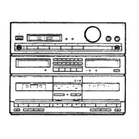
Identifies and describes all front panel buttons, knobs, displays, and connectors.

3. DISASSEMBLY

Cassette Replacement Procedures

Step-by-step guide for disassembling the cassette decks.

4. PARTS LOCATION

Component Location Views

Diagrams showing the placement of parts on front, rear, and top panels.

5. EXPLODED VIEW

Exploded Parts Diagrams and Lists

Visual breakdown of components with associated part lists.

6. ELECTRICAL PARTS LIST

Component Parts Identification

Comprehensive list of electrical components with part numbers.

7. PACKING

Packing and Component Appearance

Information on packing materials and visual appearance of key components.

8. P.C. BOARDS CONNECTION DIAGRAM

Circuit Board Interconnection Diagrams

Diagrams illustrating how different circuit boards are connected.

9. SCHEMATIC DIAGRAM

Overall Circuit Schematic

Detailed electronic schematic of the entire unit.

10. BLOCK DIAGRAM

System Block Diagram

High-level functional blocks of the device and their interconnections.

11. CIRCUIT DESCRIPTIONS

Cassette Tape Deck Operation

Explains the functionality of the cassette tape deck sections, including Dolby NR and MS.

Integrated Amplifier Circuit Details

Describes the phono, graphic equalizer, power amplifier, and protection circuits.

12. ADJUSTMENTS

Mechanical Adjustments Procedures

Guides for mechanical adjustments like pinch roller pressure and reel torque.

Electrical Adjustments Procedures

Steps for electrical adjustments including head azimuth and frequency response.

13. FOR HE, HB, S, YP TYPES

Model Type Specific Variations

Details differences in parts and power for various model types.

14. SAFETY INFORMATION

General Safety Precautions and Leakage Test

Essential safety checks and precautions for users and technicians.

Product Safety Notice and Component Replacement

Information on safety-related components and their proper replacement.

Line Voltage Selection for Specific Models

Instructions for selecting the correct line voltage for HE, YP, and HB types.

Related product manuals