Do you have a question about the Pioneer DEH-1500RXU/EW and is the answer not in the manual?
| Power Output | MOSFET 50W x 4 |
|---|---|
| Tuner | FM/AM |
| CD Playback | Yes |
| Bluetooth | No |
| Aux Input | Yes |
| USB Location | Front |
| AUX Location | Front |
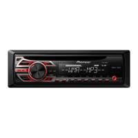
| Display Illumination | Red |
| Channels | 4 |
| RMS Power Output | 22W x 4 |
| Detachable Faceplate | Yes |
| Supported Formats | MP3, WMA |
| RCA Pre-Outs | 1 |
| Panel Type | Detachable |
| Display Type | LCD |
| Remote Control | Ready for Optional Remote Control |
Essential safety guidelines for qualified technicians during service operations.
Details on Class 1 Laser Product label and laser diode specifications.
Explanation of symbols indicating secure adjustments, settings, or cleaning.
Precautions for disassembly, electrostatic discharge, and pickup unit replacement.
Technical specifications for EW model general features, audio output, and CD player.
Technical specifications for EE model general features, audio output, and CD player.
Exploded view and parts list for the EW model's packing.
Exploded view and parts list for the EE model's packing.
Exploded view and parts list for the EW model's exterior components.
Exploded view and parts list for the EE model's exterior components.
Exploded view of the CD mechanism module with numbered parts.
Block diagram for the EW model, showing main functional units.
Reference page for understanding overall connection diagrams.
PCB layout and pin connections for the keyboard unit.
Schematic diagrams for the CD core unit and motor driver.
Visual representations of various signal waveforms for diagnosis.
PCB connection diagrams for the tuner amplifier unit.
Detailed PCB layouts for the keyboard unit.
PCB layout for the CD core unit (SIDE A).
PCB layout for the CD core unit (SIDE B).
List of miscellaneous components and resistors with part numbers.
List of capacitors and tuner amp unit components.
List of resistors, capacitors, and tuner unit parts.
Lists of capacitors, miscellaneous items, and resistors.
List of capacitors and motor unit components.
Cautions for CD adjustment and instructions for entering test mode.
Method for checking the grating angle after pickup unit replacement.
List of error codes, their displayed values, and potential causes.
Step-by-step instructions for disassembling the unit.
Instructions for assembling the keyboard unit.
Steps to remove upper/lower frames, dampers, and guide arm assembly.
Procedures for removing the CD core unit and roller arm assembly.
Steps for removing the pickup unit and load carriage motor assembly.
Description of pin functions for the rear panel connector.
Detailed pin functions and operations for PE5329A/PE5330A ICs.
Pin functions and operations for the PD6340A IC.
Detailed pin functions and operations for the UPD63712GC IC.
Pin functions and operations for the BA5996FP IC.
Pinout and explanation for the EW model's FM/AM tuner unit.
Pinout and explanation for the EE model's FM/AM tuner unit.
Diagram showing segments and common pins for the EW model LCD.
Diagram showing segments and common pins for the EE model LCD.
Flowchart illustrating the power-on sequence and initial operations.
Instructions for cleaning CD pickup lenses with specified tools.
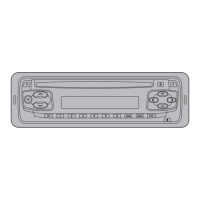
Description of all head unit buttons and their functions for the EW model.
Description of all head unit buttons and their functions for the EE model.
Guide to tuning into radio stations and storing frequencies.
Instructions for playing, repeating, and pausing CD playback.
Wiring diagram illustrating component connections for the EW model.
Wiring diagram illustrating component connections for the EE model.