Do you have a question about the Pioneer DEH-2100UB and is the answer not in the manual?
General safety guidelines for servicing the unit, including handling ICs and connectors.
Guidelines for using lead-free solder and appropriate soldering iron temperatures.
Procedures and items to confirm after completing repairs to ensure product quality.
Flowchart illustrating the unit's power-on operational sequence and communication checks.
Table listing error codes, their classes, displayed codes, and potential causes.
Procedure to enter and operate the display test mode for checking LCD segments.
Flowchart and explanation of the CD test mode for mechanism adjustments.
Step-by-step instructions and diagram for removing the CD mechanism module.
Step-by-step instructions and diagram for removing the tuner amplifier unit.
Cautions and test mode procedures for adjusting the CD mechanism module's settings.
Procedure to check grating angle after replacing the pickup unit.
| MP3 playback | Yes |
|---|---|
| DVD Video playback | No |
| Preset stations quantity | 24 |
| Output power | 200 W |
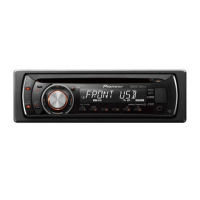
| Product color | Black |
| Disc types supported | CD-R, CD-RW |
| Display type | LCD |
| File type | MP3, WAV, WMA |
| I/O ports | 1 x USB 1 x Aux in 1 x RCA Preout |
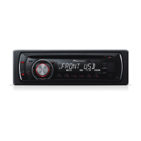
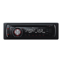
| Key illumination color | Red |
| Number of optical discs | 1 discs |