Do you have a question about the Pioneer DEH-2350UB/XNES and is the answer not in the manual?
| CD Playback | Yes |
|---|---|
| USB Port | Yes |
| Aux Input | Yes |
| Bluetooth | No |
| Detachable Faceplate | Yes |
| Channels | 4 |
| CD-R/RW Playback | Yes |
| Remote Control | Optional |
| Preset EQ | Yes |
| Subwoofer Output | Yes |
| Power Output | 50 Watts x 4 Channels |
| Tuner | AM/FM Tuner |
| USB Compatibility | MP3, WMA |
| Display Type | LCD |
| Equalizer | Yes |
| Supported Audio Formats | MP3, WMA |
| Preamp Outputs | 1 (Rear) |
| Dimensions (W x H x D) | 178mm x 50mm x 160mm |
| RMS Power Output | 22 Watts x 4 Channels |
Precautions for servicing, including laser safety and handling fragile ICs.
Conform to regulations and maintain a safe servicing environment.
Ensure optimum adjustments and proper application of lubricants.
Clean the unit and set shipping mode or screws for transit.
Conform to regulations and follow safety instructions during servicing.
Guidelines for using lead-free solder and appropriate soldering iron temperatures.
Technical specifications including general, USB, tuner, and audio parameters.
Information on supported disc and content formats for playback.
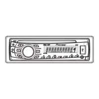
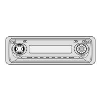
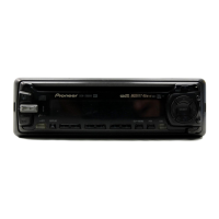
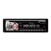
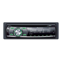
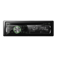
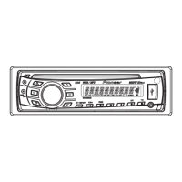
Description of head unit buttons, display indicators, and their functions.
Details on the operation of buttons on the remote control unit.
Diagrams showing how to connect the unit, power cord, and optional amplifier.
Procedures and items to confirm after servicing to ensure product quality.
Diagrams indicating the physical locations of the Tuner Amp, Keyboard, and CD Core units.
List of specific jigs, greases, and cleaning procedures for service operations.
Block diagrams illustrating the internal structure of major unit components.
Flowchart for power-on operation and source key operability checks.
List of CD error codes, their meanings, and possible causes for troubleshooting.
Detailed description of connector pin functions on the rear of the unit.
Troubleshooting guide for USB device connection and playback errors.
Procedure to enter and use the display test mode for system checks.
Flowchart and operations for entering and performing CD test mode.
Steps for removing the front panel and CD mechanism module.
Procedure for safely removing the Tuner Amp Unit from the chassis.
Instructions for disassembling and assembling the unit's panel parts.
Correct and incorrect methods for handling the CD mechanism unit to prevent distortion.
Steps for removing the Pickup Unit and moving it to the outer circumference.
Cautions and test mode operations for performing CD mechanism adjustments.
Procedure to check grating angle after changing the pickup unit.
Procedure to confirm PCL output and check the resonator if clock signal is out of range.
Exploded view illustrating the packing components and assembly.
Exploded view showing the external parts of the unit.
Exploded view detailing the parts of the CD mechanism module.
Detailed schematic diagram of the Tuner Amp Unit.
Detailed schematic diagram of the Keyboard Unit.
Detailed schematic diagram of the CD Core Unit.
Illustrations of signal waveforms for various CD core unit operations.
Layout diagram showing component placement on the Tuner Amp Unit PCB.
Layout diagram showing component placement on the Keyboard Unit PCB.
Layout diagram showing component placement on the CD Core Unit PCB.
List of ICs, transistors, and other miscellaneous electrical components.
List of resistors with their circuit symbols, part numbers, and locations.
List of capacitors with their circuit symbols, part numbers, and locations.
List of diodes, LEDs, connectors, and other components.