Do you have a question about the Pioneer DEH-23UB/XSUC and is the answer not in the manual?
| Power Output | 50 W x 4 |
|---|---|
| USB Port | Yes |
| Bluetooth | No |
| CD Playback | Yes |
| Audio Formats Supported | MP3, WMA, WAV |
| Display Type | LCD |
| DIN Size | 1-DIN |
| RMS Power Output | 22 W x 4 |
| AUX Input | Yes |
| Remote Control | Yes |
| Tuner | AM/FM |
| Equalizer | 5-Band |
Safety precautions for product handling and repair.
Procedures for optimizing product performance and confirming specifications.
Guidance on using specified lubricants and adhesives for repairs.
Instructions for cleaning parts to restore performance.
Procedures for setting shipping mode or installing screws for transit protection.
General precautions and safety guidelines for servicing the unit.
Specific instructions and precautions for using lead-free solder during repairs.
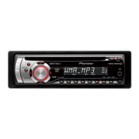
Technical specifications for the DEH-23UB/XSUC model.
Supported disc and content file formats for the unit.
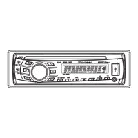
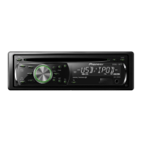
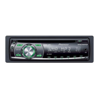
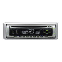
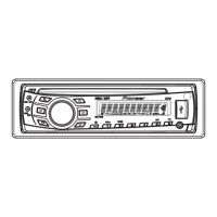
Description of the unit's front panel features and remote control functions.
Diagrams illustrating power, speaker, and optional component connections.
Essential checks to perform after completing service procedures.
Identification and location of the main printed circuit boards (PCBs) within the unit.
List of specialized jigs and tools required for specific service tasks.
Procedures for cleaning unit components before shipping.
Overall block diagram illustrating the unit's internal system architecture.
Flowchart detailing the power-on operation sequence and checks.
List of CD error codes, their meanings, and possible causes.
Description of the function of each connector on the unit's rear panel.
Procedure to enter and use the display test mode for checking system information.
Detailed test modes for CD mechanism adjustment and checks.
Step-by-step guide to removing the front panel assembly.
Procedure for removing the CD mechanism module from the unit.
Instructions for removing the Tuner Amp Unit.
Steps for disassembling the front panel components.
Detailed procedure for removing the pickup (PU) unit from the CD mechanism.
Procedures and precautions for adjusting the CD mechanism module.
Method to check grating angle after replacing the pickup unit.
Procedure to confirm PCL output signal for IC601.
Exploded view and parts list for the product's packing and accessories.
Exploded view of the unit's exterior components and their part numbers.
Exploded view and parts list for the CD mechanism module.
Schematic diagram for the Tuner Amp Unit, showing component layout.
Schematic diagram for the Keyboard Unit, detailing its circuitry.
Schematic diagram for the CD Core Unit, illustrating its internal connections.
Oscilloscope waveforms for various signal points within the CD Core Unit.
PCB connection diagram for the Tuner Amp Unit, showing component placement.
PCB connection diagram for the Keyboard Unit, showing component placement.
PCB connection diagram for the CD Core Unit, showing component placement.