EasyManua.ls Logo

Pioneer DEH-2770MP User Manual

Pioneer DEH-2770MP
72 pages
To Next Page IconTo Next Page
Page #1 background imageLoading...
Page #1 background image
ORDER NO.
PIONEER CORPORATION 4-1, Meguro 1-chome, Meguro-ku, Tokyo 153-8654, Japan
PIONEER ELECTRONICS (USA) INC. P.O. Box 1760, Long Beach, CA 90801-1760, U.S.A.
PIONEER EUROPE NV Haven 1087, Keetberglaan 1, 9120 Melsele, Belgium
PIONEER ELECTRONICS ASIACENTRE PTE. LTD. 253 Alexandra Road, #04-01, Singapore 159936
PIONEER CORPORATION 2004
DEH-2790MP/XN/ID
CRT3396
HIGH POWER CD/MP3/WMA PLAYER WITH FM/AM TUNER
DEH-2790MP
/XN/ID
DEH-2750MP
/XN/GS
DEH-2770MP
/XN/CS
This service manual should be used together with the following manual(s):
Model No. Order No. Mech.Module Remarks
CX-3158 CRT3394 S10.1AAC CD Mech. Module : Circuit Description, Mech. Description, Disassembly
For details, refer to "Important Check Points for Good Servicing".
K-ZZA. NOV. 2004 Printed in Japan
w
w
w
.
x
i
a
o
y
u
1
6
3
.
c
o
m
Q
Q
3
7
6
3
1
5
1
5
0
9
9
2
8
9
4
2
9
8
T
E
L
1
3
9
4
2
2
9
6
5
1
3
9
9
2
8
9
4
2
9
8
0
5
1
5
1
3
6
7
3
Q
Q
TEL 13942296513 QQ 376315150 892498299
http://www.xiaoyu163.com

Other manuals for Pioneer DEH-2770MP

Question and Answer IconNeed help?

Do you have a question about the Pioneer DEH-2770MP and is the answer not in the manual?

Pioneer DEH-2770MP Specifications

General IconGeneral
BrandPioneer
ModelDEH-2770MP
CategoryCar Receiver
LanguageEnglish

Summary

Service Manual

Manual Compatibility Information

Mentions compatibility with other manuals.

Servicing Guidelines Reference

Points to a specific section for servicing guidelines.

SAFETY INFORMATION

Service Precaution

Provides essential precautions for servicing safety.

Important Check Points for Good Servicing

Product Safety Measures

Details safety measures and guidelines to follow during product repair.

Maintenance and Adjustment Procedures

Covers adjustments, lubricants, parts, cleaning, and shipping preparation.

Specifications

General Specifications

Lists general specifications like power, dimensions, and weight.

Audio and Tuner Specifications

Details audio output power, tuner specs, and frequency response.

CD Player Specifications

Lists specifications related to the CD player functionality.

Exploded Views and Parts List

Packing Information

Illustrates the packing configuration of the unit and its components.

Parts List Notes

Contains important notes regarding parts marking and application of lubricants.

Packing Section Parts List

Contrast Table for Parts

Exterior Views

Exterior Parts List

Exterior Parts Contrast Table

CD Mechanism Module

CD Mechanism Module Parts List

Block Diagrams and Schematics

Block Diagram Overview

Shows the overall functional blocks and their interconnections.

Tuner Amp Unit Block Diagram

Block diagram for the tuner amplifier unit, showing signal flow.

CD Core Unit Block Diagram

Block diagram for the CD core unit, illustrating its functional components.

System Controller Pin Functions

Keyboard Unit Pin Functions

Overall Connection Diagram (Guide Page)

Diagram Notes

Provides important notes regarding symbols used in diagrams and part designation.

Keyboard Unit

Keyboard Unit PCB Layout

CD Mechanism Module (Guide Page)

CD Core Unit Grounding and Switches

Lists the switches within the CD core unit and their functions.

CD Core Unit Schematic

CD Core Unit and Pickup Unit Schematics

CD Core Unit Schematics

Detailed schematic diagrams for the CD core unit.

Pickup Unit Schematics

Detailed schematic diagrams for the pickup unit.

Waveform Analysis

Waveform Measurement Notes

Explains waveform measurement points and reference voltage.

PCB Connection Diagrams

Tuner Amp Unit PCB Connection

PCB layout showing connections for the tuner amplifier unit.

PCB Diagram Notes

Notes on interpreting PCB diagrams and part designations.

Tuner Amp Unit PCB Layout (Side A)

Tuner Amp Unit PCB Layout (Side B)

Keyboard Unit PCB Layout

Keyboard Unit PCB Layout (Side A)

PCB layout illustrating component placement for the keyboard unit.

Keyboard Unit PCB Layout (Side B)

CD Core Unit PCB Layout

CD Core Unit PCB Layout (Side A)

PCB layout showing component placement and connections for the CD core unit.

CD Core Unit PCB Layout (Side B)

Electrical Parts List

Parts List Notes

Contains notes on omitted parts, chip components, and part marking significance.

Miscellaneous Components

Lists ICs, transistors, diodes, inductors, oscillators, and other miscellaneous parts.

Resistor and Capacitor Lists

Lists resistors and capacitors with their circuit symbols, part numbers, and values.

Keyboard Unit Parts

Details parts specifically for the keyboard unit, including miscellaneous items and resistors.

Keyboard Unit Miscellaneous Parts

Keyboard Unit Resistor List

Component Identification

Capacitor List

Component Identification

Miscellaneous Parts List

CD Adjustment Procedures

CD Adjustment Precautions

Provides critical warnings and guidelines for safe and accurate adjustment procedures.

CD Adjustment Test Mode

Explains how to enter and use the test mode for CD mechanism adjustment.

Adjustment Flow Chart

Flow Chart Key and Operations

Explains the meaning of symbols and keys used in the flow chart.

Grating Check After Pickup Unit Change

Grating Check Procedure

Step-by-step guide for checking the grating angle using test mode and oscilloscope.

Grating Check Notes and Hints

Explains waveform wobble and suggests reloading the disc.

Grating Waveform Examples

Error Mode Diagnostics

Error Message Display and Codes

Explains the purpose and display format of error messages and lists error codes.

System Microcomputer Test Program

PCL Output Check

Details how to check the PCL output signal frequency for microcomputer testing.

General Information and Diagnosis

Disassembly Instructions

Step-by-step instructions on how to disassemble the unit.

Component Removal Procedures

Instructions for removing the case, grille, tuner amp, and CD mechanism.

Mechanism Unit Handling and Frame Removal

Pickup Unit Removal Procedure

Connector Function Description

Parts List

Integrated Circuits (ICs) Pin Functions

Lists Integrated Circuits (ICs) with their pin functions, I/O, and operations.

IC PE5447A Pin Functions

IC PD6340A Pin Functions

IC UPD63763GJ Pin Functions

IC UPD63763GJ Pin Functions

IC PE5454A Pin Functions

IC PE5454A Pin Functions

FM/AM Tuner Unit Interface Description

Display Unit

LCD (CAW1848) Layout

Shows the layout and segments of the LCD display.

Operational Flow Chart

Power On Sequence Flow Chart

Outlines the sequence of operations during power-on.

Cleaning Procedures

Cleaning Portions and Tools

Lists the parts that require cleaning before shipping and the tools to use.

Unit Operations

Head Unit Button Functions

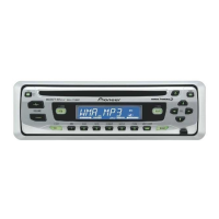
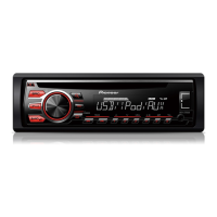
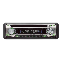
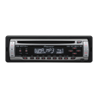
Describes the functions of the buttons on the head unit.

Playing a CD

CD Playback Operations

Instructions for inserting, playing, repeating, random, and scanning tracks of a CD.

Pausing CD Playback

Front Panel Fixing Screws

Connection Diagram

Power Amplifier Connections

Shows connections for an optional power amplifier.

RCA Pin Plug Connections

Details connections using RCA pin plugs.

System Remote Control Wiring

Wiring for system remote control.

Jigs List

Jig Identification and Remarks

Lists the names, numbers, and purposes of the jigs used for checks.

Related product manuals