Do you have a question about the Pioneer DEH-345 and is the answer not in the manual?
Precautions for handling pickup units, internal ICs, and service pickup units.
Precautions for laser diode, minimum distance from focus lens, and not viewing laser beam.
Exploded view of packing components and their list.
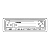
Exploded view of exterior parts and their list.
Exploded view of the CD mechanism module components.
Overall connection diagram for the unit, serving as a guide.
Schematic diagram of the CD mechanism module as a guide.
Schematic diagram for the FM/AM tuner unit.
Schematic diagram for the keyboard unit.
PCB connection diagram for the tuner amp unit.
PCB connection diagram for the FM/AM tuner unit.
PCB connection diagram for the CD mechanism module.
PCB connection diagram for the keyboard unit.
Procedures for adjusting the tuner section of the unit.
Precautions and procedures for CD player section diagnosis and testing.
Flow chart illustrating test mode operations for the CD player.
Procedure to check pickup unit grating angle after replacement.
General overview of parts used in the unit.
Details IC pin functions and block diagrams for key components.
Diagram showing LCD segment assignments and display layout.
Step-by-step instructions for disassembling the unit.
Explanation of error codes and how to enter test mode.
Block diagram illustrating the unit's functional relationships.
Diagram showing external connections for power, speakers, and antenna.
Detailed technical specifications for all unit sections.
| Brand | Pioneer |
|---|---|
| Model | DEH-345 |
| Category | Car Receiver |
| Language | English |