Do you have a question about the Pioneer DEH-4000UB/XS/EW5 and is the answer not in the manual?
| DIN Size | Single DIN |
|---|---|
| Power Output | 50 Watts x 4 Channels |
| RMS Power Output | 22 Watts x 4 Channels |
| Built-in Amplifier | Yes |
| Tuner | AM/FM |
| CD Playback | Yes |
| USB Input | Yes |
| Aux Input | Yes |
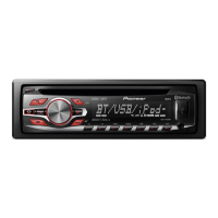
| Bluetooth | No |
| Display Type | LCD |
| Sub Preamp Output | Yes |
| Detachable Face | Yes |
| High-Pass Filter | Yes |
| Low-Pass Filter | Yes |
| Clock | Yes |
| Dimensions (W x H x D) | 178 x 50 x 160 mm |
| HD Radio | No |
| Memory Card Reader | No |
| MP3 Playback | Yes |
| WMA Playback | Yes |
| ID3 Tag Display | Yes |
| Peak Output (CTA-2006) | 50W x 4 |
| Preamp Voltage | 2 volts |
| Satellite Radio Ready | Yes |
| Illumination | Variable Color |
| Button Color | Variable Color |
General safety precautions for servicing, including laser diode safety.
Procedures ensuring product safety regulations and a safe servicing environment.
General precautions for safe handling and servicing of the unit.
Detailed technical specifications for the EW5 model.
Diagram showing external connections for the EW5 model.
Diagram illustrating external connections for ES and CN5 models.
Overall system block diagram showing major functional units.
Flowchart illustrating the unit's power-on operation sequence.
Explains error modes, display examples, and detailed error codes for troubleshooting.
Lists USB error messages, their causes, and recommended actions.
Procedures and cautions for using the CD test mode for adjustment.
Steps for removing keyboard unit, holder, case, and panel.
Comprehensive guide for checking grating angle after PU unit replacement, including notes and methods.
Main connection diagram illustrating how different units are interconnected.
Schematic diagram for the CD mechanism module.