Do you have a question about the Pioneer DEH-5200SD/XNEW5 and is the answer not in the manual?
| Detachable Face | Yes |
|---|---|
| Tuner | AM/FM |
| Bluetooth | No |
| CEA-2006 Compliant | Yes |
| MP3 Playback | Yes |
| WMA Playback | Yes |
| ID3 Tag Display | Yes |
| FM Presets | 18 |
| AM Presets | 6 |
| RDS Tuner | Yes |
| Sub Preamp Output | Yes |
| Bass Boost | Yes |
| Remote Control | Yes |
| Preset EQ | Yes |
| High-Pass Filter | Yes |
| Low-Pass Filter | Yes |
| Subwoofer Output | Yes |
| Preset Stations | 24 |
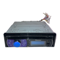
| Model | DEH-5200SD |
| Maximum Power Output | 50W x 4 |
| RMS Power Output (CTA-2006) | 14W x 4 |
| Media Playback | CD |
| Equalizer | Yes |
| Auxiliary Input | Yes |
| USB Input | Yes |
| Memory Card Slot | SD Card |
| iPod Compatibility | Optional Adapter Required |
| Steering Wheel Control | Optional Adapter Required |
| DIN Size | Single DIN |
| Peak Output | 50W x 4 |
General guidelines for safe and proper servicing procedures, including laser safety.
Conforming to regulations and maintaining a safe servicing environment.
Ensuring optimum performance through proper adjustments and confirmations.
General precautions for servicing, including power handling and ESD protection.
Guidelines for using lead-free solder and appropriate soldering techniques.
Technical details including power, audio, USB, SD, and tuner capabilities.
Procedures to verify product quality and confirm customer complaints are resolved.
Flowchart illustrating the power-on sequence and communication checks.
Details CD-related error codes, their classification, and possible causes.
Procedure to enter and operate the CD Test Mode for mechanism adjustments.
Guides to select and operate Display Test Mode for screen checks.
Step-by-step instructions for removing the main case of the unit.
Procedure to detach and remove the CD mechanism module from the unit.
Procedure to detach and remove the Tuner Amp Assy from the unit.
Guidelines on correctly holding the mechanism unit to prevent damage.
Instructions on correct PU handling, emphasizing proper grip points.
Precautions for voltage adjustments and procedures for entering/exiting CD Test Mode.
Steps to check grating angle using oscilloscope and test mode after PU replacement.
Procedure to confirm PCL output signal frequency for clock signal verification.
Exploded view and parts list for the packing and accessories of the unit.
Exploded view of the unit's exterior components, part 1.
Exploded view of the unit's exterior components, part 2.
Exploded view of the CD mechanism module, showing all internal parts and their assembly.
Schematic diagram for the Tuner Amp Assy (Main), serving as a guide page.
Illustrates essential waveforms for diagnosing CD operations like loading and search.
Diagram showing component placement and connector pinouts for the Tuner Amp Assy PCB.
PCB layout diagram for the Keyboard Unit, showing components and connectors.
PCB layout diagram for the CD Core Unit (S11STD-DOUT), showing components and connectors.
List of various electronic components including ICs, transistors, diodes, and connectors.