EasyManua.ls Logo

Pioneer DEH-M6017ZH User Manual

Pioneer DEH-M6017ZH
71 pages
To Next Page IconTo Next Page
Page #1 background imageLoading...
Page #1 background image
PIONEER CORPORATION 4-1, Meguro 1-Chome, Meguro-ku, Tokyo 153-8654, Japan
PIONEER ELECTRONICS SERVICE INC. P.O.Box 1760, Long Beach, CA 90801-1760 U.S.A.
PIONEER EUROPE NV Haven 1087 Keetberglaan 1, 9120 Melsele, Belgium
PIONEER ELECTRONICS ASIACENTRE PTE.LTD. 253 Alexandra Road, #04-01, Singapore 159936
C PIONEER CORPORATION 2001
K-ZZS. JAN. 2001 Printed in Japan
ORDER NO.
CRT2657
MULTI-CD CONTROL CD PLAYER WITH RDS TUNER
DEH-M6006ZH X1P/EW
Service
Manual
HONDA
VEHICLE DESTINATION PRODUCED AFTER HONDA PART No. ID No. PIONEER MODEL No.
CIVIC 5door EUROPE March 2001 39100-S6A-G500 DEH-M6006ZH/X1P/EW
ACCORD EUROPE February 2001 39100-S1A-E100 DEH-M6017ZH/EW
DEH-M6006ZH/X1P/EW
- This service manual should be used together with the following manual(s):
Model No. Order No. Mech. Module Remarks
CX-958 CRT2423 S8.1 CD Mech. Module:Circuit Description, Mech.Description, Disassembly
DEH-M6017ZH EW
CONTENTS
1. SAFETY INFORMATION............................................2
2. EXPLODED VIEWS AND PARTS LIST ......................3
3. BLOCK DIAGRAM AND SCHEMATIC DIAGRAM ..10
4. PCB CONNECTION DIAGRAM................................30
5. ELECTRICAL PARTS LIST........................................40
6. ADJUSTMENT .........................................................49
7. GENERAL INFORMATION.......................................54
7.1 DIAGNOSIS .......................................................54
7.1.1 ERROR MESSAGES.................................54
7.1.2 DISASSEMBLY.........................................55
7.1.3 CONNECTOR FUNCTION DESCRIPTION ......60
7.2 PARTS ................................................................61
7.2.1 IC ...............................................................61
7.2.2 DISPLAY ...................................................67
7.3 OPERATIONAL FLOW CHART..........................68
8. OPERATIONS AND SPECIFICATIONS ....................71
Question and Answer IconNeed help?

Do you have a question about the Pioneer DEH-M6017ZH and is the answer not in the manual?

Pioneer DEH-M6017ZH Specifications

General IconGeneral
CD PlaybackYes
MP3 PlaybackYes
BluetoothNo
Channels4
RMS Power Output22W x 4
WMA PlaybackYes
Remote ControlYes
Power Output50W x 4
TunerFM/AM
AUX InputYes

Summary

1. SAFETY INFORMATION

Safety Precautions for Service

Essential safety measures for technicians during repairs.

Laser Diode Specifications

Details on laser radiation for safe service procedures.

2. EXPLODED VIEWS AND PARTS LIST

2.1 PACKING

Exploded view and parts list for product packaging.

2.2 EXTERIOR(DEH-M6006ZH)

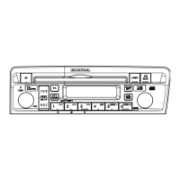
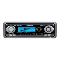
External parts diagram for DEH-M6006ZH model.

2.3 EXTERIOR(DEH-M6017ZH)

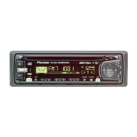
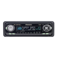
External parts diagram for DEH-M6017ZH model.

2.4 CD MECHANISM MODULE

Exploded view of the CD mechanism module.

3. BLOCK DIAGRAM AND SCHEMATIC DIAGRAM

3.1 BLOCK DIAGRAM

Overall block diagram of the tuner amp unit and related systems.

3.2 OVERALL CONNECTION DIAGRAM

Guide page for overall connection diagrams.

3.4 CD MECHANISM MODULE

Block diagram for CD mechanism module and control unit.

Waveforms

Waveform Analysis and Interpretation

Visual representations and explanations of key signal waveforms.

4. PCB CONNECTION DIAGRAM

4.1 TUNER AMP UNIT

PCB connection diagram for the Tuner Amp Unit.

4.2 KEYBOARD UNIT (DEH-M6006ZH)

PCB connection diagram for the Keyboard Unit.

4.3 KEYBOARD UNIT (DEH-M6017ZH)

PCB connection diagram for the Keyboard Unit.

4.4 CD MECHANISM MODULE

PCB connection diagram for the CD Mechanism Module.

5. ELECTRICAL PARTS LIST

IC Components List

List of Integrated Circuits with part numbers.

Resistors List

Comprehensive list of resistors with part numbers.

Capacitors List

Comprehensive list of capacitors with part numbers.

Keyboard Unit Parts

Parts list for the Keyboard Unit.

Tuner Amp Unit Parts

Parts list for the Tuner Amp Unit.

6. ADJUSTMENT

6.1 CD ADJUSTMENT

Procedures for adjusting CD player functions.

6.2 GRATING CHECK AFTER PICKUP REPLACEMENT

Procedure to check grating after pickup unit change.

6.3 CLOCK ADJUSTMENT

Steps for clock signal adjustment.

7. GENERAL INFORMATION

7.1 DIAGNOSIS

Information on diagnosing common errors and issues.

7.1.2 DISASSEMBLY

Step-by-step guide for disassembling the unit.

7.1.3 CONNECTOR FUNCTION DESCRIPTION

Description of connector functions for troubleshooting.

7.2 PARTS

7.2.1 IC

List of Integrated Circuits with part numbers.

7.2.2 DISPLAY

Diagram of the LCD display segments and connections.

7.3 OPERATIONAL FLOW CHART

Flow chart detailing the power-on operation sequence.

8. OPERATIONS AND SPECIFICATIONS

8.1 OPERATIONS(DEH-M6006ZH)

Explanation of operational controls for the DEH-M6006ZH.

8.2 OPERATIONS(DEH-M6017ZH)

Explanation of operational controls for the DEH-M6017ZH.

8.2 SPECIFICATIONS

Technical specifications for the device.

Related product manuals