Do you have a question about the Pioneer DEH-P3600MPB and is the answer not in the manual?
Precautions for safe service of the unit, including laser safety.
Details on laser radiation fields and wavelength.
Precautions for handling the CD player during service.
Exploded view and parts list for the packing components.
Exploded view and parts list for exterior components.
Exploded view and parts list for the CD mechanism module.
Overall block diagram of the system.
Overall connection diagram for the unit.
Block diagram for the keyboard unit.
Block diagram for the CD mechanism module.
PCB connection diagram for the Tuner Amp Unit.
PCB connection diagram for the Panel Unit.
PCB connection diagram for the Keyboard Unit.
PCB connection diagram for the CD Core Unit.
Procedures for adjusting the CD mechanism module.
Procedure to check grating angle after PU unit replacement.
Error messages and their causes for CD operation.
Information on diagnosing issues, including disassembly.
Description of connector pin functions.
List of electronic parts, including ICs.
Details on LCD display segments and common connections.
Flow chart illustrating operational sequences.
Procedures for cleaning the CD pickup lenses.
Basic steps for playing a CD.
| Channels | 4 |
|---|---|
| Max Power Output | 50 W x 4 |
| RMS Power Output | 22 W x 4 |
| Sub Preamp Output | Yes |
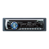
| CD Player | Yes |
| CD Signal-to-Noise | 94 dB |
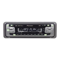
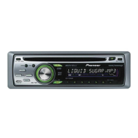
| MP3 Playback | Yes |
| WMA Playback | Yes |
| CD-R Playback | Yes |
| CD-RW Playback | Yes |
| ID3 Tag | Yes |
| USB Input | No |
| Auxiliary Input | Yes |
| Bluetooth | No |
| Tuner Bands | AM/FM |
| FM Presets | 18 |
| AM Presets | 6 |
| Detachable Faceplate | Yes |
| Display Type | LCD |
| EQ Settings | 3-Band |
| Subwoofer Output | Yes |
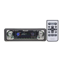
| Remote Control | Yes |
| CEA-2006 Compliant | Yes |
| DIN Size | 1 DIN |
| Preamp Voltage | 2.2V |
| Preset EQ | 5 |