Do you have a question about the Pioneer DEH-P4650MP/XM/ES and is the answer not in the manual?
| CD Playback | Yes |
|---|---|
| MP3 Playback | Yes |
| USB Port | No |
| Bluetooth | No |
| Sub Preamp Output | Yes |
| ID3 Tag Display | Yes |
| XM Radio Ready | Yes |
| HD Radio | No |
| iPod Compatibility | No |
| Memory Card Slot | No |
| Remote Control | Yes |
| Channels | 4 |
| Built-in DSP | No |
| Max Power Output | 50 W x 4 |
| Tuner | FM/AM |
| DIN Size | 1 DIN |
| RMS Power Output | 22W x 4 |
General safety advice for service technicians regarding the use of this manual.
Warning about chemicals known to cause cancer or birth defects as per Proposition 65.
Specific safety steps for servicing the CD player unit, including power and ESD precautions.
Conformance to regulations and safety during servicing procedures.
Importance of performing optimum adjustments and proper cleaning for performance.
Procedures for shipping mode and proper use of lubricants, glues, and parts.
Basic power, dimension, and weight specifications for the unit.
Audio output, impedance, and equalizer specifications.
Specifications for CD playback features, formats, and performance.
FM and AM reception sensitivity and performance specifications.
General notes regarding parts marking, availability, and application of lubricants.
Exploded view and parts list for the packing components.
List of available owner's manuals and installation manuals for different models.
Detailed list of parts for the exterior assembly, including screws, connectors, and panels.
Detailed parts list for the CD mechanism module, covering gears, springs, motors, and more.
High-level functional overview of the unit's circuits and component interactions.
Diagram showing how major components connect to the main unit.
Diagram illustrating the keyboard unit components and their connections.
Detailed schematic and diagrams for the CD mechanism module.
Analysis of various operational waveforms for troubleshooting and performance checks.
PCB layout and component placement for the tuner amplifier unit.
PCB layout and component placement for the panel unit.
PCB layout and component placement for the keyboard unit.
PCB layout and component placement for the CD core unit.
Important notes and definitions for the parts list, including chip components.
List of electrical components (ICs, transistors, resistors, etc.) for the Tuner Amp Unit.
Various components not fitting other categories, such as regulators and switches.
List of resistors used in the unit, with part numbers.
Procedures and cautions for adjusting the CD mechanism module.
Critical safety advice, test mode explanations, and warnings for adjustments.
Explains flowchart symbols and test mode operations for CD adjustment.
Explains why and when to check the grating, and symptoms of misalignment.
Lists required measuring tools and points for checking the pickup unit grating.
Step-by-step guide for checking the pickup unit's grating angle.
Additional notes and hints regarding grating waveform wobble and disc reloading.
Explains how error codes are displayed on the unit's LCD.
Detailed table of error codes, their classes, and potential causes.
Details how to check the system microcomputer's PCL output frequency.
Diagnosis overview and step-by-step instructions for disassembling the unit.
Instructions on how to properly hold and handle the mechanism unit.
Procedure for removing the upper and lower frames of the unit.
Steps for preparation, solder application, cable disconnection, and clamp mode setting.
Instructions for removing lead wires, washer, styling holder, change arm, and lock arm.
Steps for lifting the feed screw and setting the planet gear position.
Describes pin functions for power supply, IP-BUS, and remote control connectors.
Describes pin functions for antenna jack, front/rear outputs, and remote control.
List of integrated circuits with pin names, I/O, format, and function.
Detailed pin functions for the PD6340A IC.
Detailed pin functions for the UPD63761GJ IC.
Diagrams showing segment assignments for the LCD display.
Explains flowchart symbols and test mode operations for initialization.
Recommended procedure and tools for cleaning the CD pickup lenses.
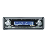
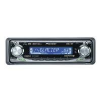
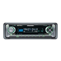
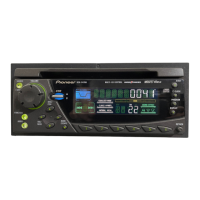
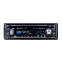
Explanation of the buttons and functions on the main unit's head unit.
Basic steps for inserting and playing a CD using the player.
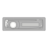
Instructions for attaching the front panel using holders and fixing screws.
Wiring diagram showing connections to speakers, power amp, and other components.