EasyManua.ls Logo

Pioneer DEH-P4950MP/XU/CN5 User Manual

Pioneer DEH-P4950MP/XU/CN5
68 pages
To Next Page IconTo Next Page
Page #1 background imageLoading...
Page #1 background image
ORDER NO.
PIONEER CORPORATION 4-1, Meguro 1-chome, Meguro-ku, Tokyo 153-8654, Japan
PIONEER ELECTRONICS (USA) INC. P.O. Box 1760, Long Beach, CA 90801-1760, U.S.A.
PIONEER EUROPE NV Haven 1087, Keetberglaan 1, 9120 Melsele, Belgium
PIONEER ELECTRONICS ASIACENTRE PTE. LTD. 253 Alexandra Road, #04-01, Singapore 159936
PIONEER CORPORATION 2006
DEH-P4950MP/XU/CN5
CRT3817
CD RECEIVER
DEH-P4950MP
/XU/CN5
This service manual should be used together with the following manual(s):
Model No. Order No. Mech.Module Remarks
CX-3195 CRT3815 S10.5COMP2 CD Mech. Module : Circuit Descriptions, Mech. Descriptions, Disassembly
For details, refer to "Important Check Points for Good Servicing".
K-ZZA. OCT. 2006 Printed in Japan
Question and Answer IconNeed help?

Do you have a question about the Pioneer DEH-P4950MP/XU/CN5 and is the answer not in the manual?

Pioneer DEH-P4950MP/XU/CN5 Specifications

General IconGeneral
BrandPioneer
ModelDEH-P4950MP/XU/CN5
CategoryCar Receiver
LanguageEnglish

Summary

Service Manual

CD Receiver DEH-P4950MP/XU/CN5

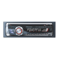
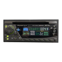
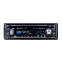
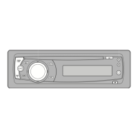
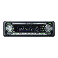
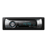
Main model identification and title of the service manual.

Safety Information

Safety Precautions for Servicing

Guidelines for safe repair procedures and handling of laser diodes.

Service Precautions

Important steps to prevent damage and ensure safety during repair work.

Important Check Points for Good Servicing

Product Safety

Conformance to regulations, safe environment, and proper repair practices.

Adjustments

Procedures for optimizing product performance and confirming specifications.

Lubricants, Glues, and Replacement Parts

Guidance on using specified substances and applying correct amounts.

Specifications

Exploded Views and Parts List

Packing Section Parts List

List of parts included in the product packaging.

Exterior Section Parts List

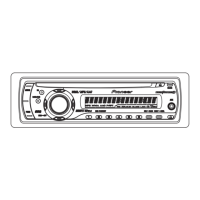
List of external components and their part numbers.

CD Mechanism Module Section Parts List

List of components for the CD mechanism module.

Block Diagram and Schematic Diagram

Block Diagram

High-level overview of the system's functional blocks and signal flow.

Overall Connection Diagram

Visual representation of how different units are connected within the system.

Keyboard Unit Diagram

Detailed diagram of the keyboard unit and its component layout.

CD Mechanism Module Diagram

Schematic diagram illustrating the CD mechanism module's internal connections.

Waveforms

PCB Connection Diagram

Tuner Amp Unit PCB

Printed circuit board layout for the tuner amplifier unit.

Keyboard Unit PCB

Printed circuit board layout for the keyboard unit.

CD Core Unit PCB

Printed circuit board layout for the CD core unit.

Electrical Parts List

Adjustment

CD Adjustment

Procedures for adjusting the CD mechanism, including test modes and cautions.

Checking the Grating After Changing the Pickup Unit

Method to check grating angle and ensure proper PU unit function.

Error Mode

System Microcomputer Test Program

Procedures for system testing, including PCL output analysis.

General Information

Diagnosis

General diagnostic information and disassembly instructions for major units.

Connector Function Description

Details on the function of each connector on the unit.

Parts

IC Identification and Pin Functions

Identification and pin functions for integrated circuits used in the device.

Display Unit Details

Pin layout and block diagram for the LCD display unit.

FM/AM Tuner Unit Description

Explanation of symbols and connections for the FM/AM tuner unit.

Operations

Connection Diagram

Jigs List

Grease List

Related product manuals