Do you have a question about the Pioneer DEH-P5600MPXM and is the answer not in the manual?
| DIN Size | Single DIN |
|---|---|
| RMS Power Output | 22W x 4 |
| Preamp Outputs | 3 pairs |
| Sub Preamp Output | Yes |
| Display Color | Multi-Color |
| CEA-2006 Compliant | Yes |
| MP3 Playback | Yes |
| WMA Playback | Yes |
| ID3 Tag | Yes |
| Tuner Bands | AM/FM |
| FM Sensitivity | 8 dBf |
| CD Frequency Response | 5 Hz - 20 kHz |
| Channels | 4 |
| CD Player | Yes |
| Detachable Faceplate | Yes |
| Remote Control | Yes |
| Built-in Equalizer | Yes |
| Preset EQ Curves | 5 |
| High-Voltage Preouts | Yes |
| Subwoofer Control | Yes |
| IP-Bus System Control | Yes |
| CD Text Display | Yes |
| ID3 Tag Display | Yes |
| Rotary Volume Control | Yes |
| MOSFET Power IC | Yes |
| Preamp Voltage | 4V |
| RMS Power Bandwidth | 20Hz - 20kHz |
| Max Power Output | 50W x 4 |
Precautions for servicing the unit, focusing on laser diode safety.
Details laser diode radiation specifications for service.
Precautions for handling the CD pickup unit and ICs during servicing.
Exploded view and parts list for the product's packaging.
Exploded view and parts list for the external components of the unit.
Exploded view and parts list for the CD mechanism module.
Overall block diagram of the Tuner Amp and CD Core units.
Connection diagram illustrating how different units connect.
Schematic diagram for the keyboard unit.
Schematic diagram for the CD core unit.
PCB layout diagram for the Tuner Amp unit.
PCB layout diagrams for the Panel unit (Side A and B).
PCB layout diagrams for the Keyboard unit (Side A and B).
PCB layout diagram for the CD Core unit (Side A).
Procedures and cautions for adjusting the CD mechanism.
Procedure to check grating angle after replacing the pickup unit.
Lists error codes and their potential causes for the CD system.
Procedure to check clock frequency and replace the crystal if needed.
Information on diagnosing problems, including disassembly steps.
Flow chart detailing the power-on and source selection operational sequence.
Recommended cleaning tools and procedures for pickup lenses.
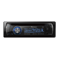
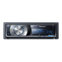
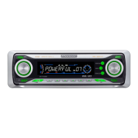
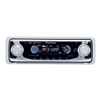
Description of the head unit controls and functions.
Basic steps for playing a CD, including panel operation and notes.