Do you have a question about the Pioneer DEH-X65BT and is the answer not in the manual?
Guidelines for qualified technicians, including power, ESD, and component handling.
Warnings related to chemical exposure, laser radiation, and product safety.
Details on laser wavelength and maximum output power.
Caution regarding incorrect battery replacement and disposal.
Specific instructions on regulations, power, ESD, pickup, and IC handling.
Guidance on using lead-free solder and appropriate soldering iron techniques.
Technical specifications for audio, CD, USB, FM/AM tuners, and Bluetooth.
Procedure for securing the front panel using a supplied screw.
Post-service checks for customer complaints, media operation, and appearance.
Diagram showing locations of Tuner Amp, Keyboard, BT, and CD Core units.
Instructions for cleaning CD pickup lenses using specified cleaning tools.
Flowchart illustrating the power-on operation sequence and checks.
List of CD error codes, classifications, and their details for diagnosis.
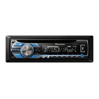
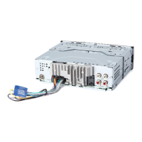
Description of antenna, wired remote, and front output connectors.
Description of rear output or subwoofer output connector pinout.
Procedure to enter and operate Display Test Mode 1 for screen and grille checks.
Checking system microcomputer version and display information in Test Mode 2.
Procedure for upgrading system MCU software using USB memory.
Flowchart and key operations for various CD mechanism tests and adjustments.
Steps to remove the front panel assembly from the unit.
Procedure for removing the CD mechanism module from the unit.
Steps for disconnecting and removing the Tuner Amp and BT units.
Warning about specific screws on the CD mechanism module during disassembly.
Instructions for disassembling specific panel components and buttons.
Steps for reassembling panel components, including springs and buttons.
Guidelines for correctly carrying the mecha unit to prevent damage or distortion.
Detailed steps and cautions for removing the pickup (PU) unit.
Important cautions and considerations for performing CD mechanism adjustments.
Procedure to enter and notes for the CD mechanism adjustment test mode.
Procedure to check grating angle after PU unit replacement and identify mal-adjustment.
Procedure to confirm PCL output signal frequency and troubleshooting for clock signal issues.
Notes regarding part availability, safety factors, and disassembly screws.
Diagrams illustrating the packing of different model variants.
List of parts included in the packing for various model numbers.
Table detailing part differences across various DEH models.
Exploded view identifying exterior parts and their corresponding numbers.
Detailed list of exterior parts with part numbers.
Table comparing exterior part differences across DEH models.
Detailed list of parts for the CD mechanism module.
Circuit diagram for the Tuner Amp Unit, including reference area maps.
Schematics for the Keyboard Unit, detailing connections and components.
Schematics for the CD Core Unit, detailing ICs and connections.
Schematics for the BT Unit, showing connections and internal circuitry.
Waveforms related to CD operations and signal analysis.
Diagram showing PCB layout and component placement for the Tuner Amp Unit.
PCB layouts for the Keyboard Unit, showing component positions.
PCB layouts for the CD Core Unit, indicating component placement.
PCB layouts for the BT Unit, showing component and connector positions.
List of components with circuit symbols, part numbers, and locations.
| Bluetooth | Yes |
|---|---|
| USB Port | Yes |
| CD Playback | Yes |
| Tuner | AM/FM |
| Display Type | LCD |
| Preamp Outputs | 3 (Front, Rear, Subwoofer) |
| Equalizer | 13-band graphic equalizer |
| DIN Size | Single DIN |
| CEA-2006 Compliant | Yes |
| Subwoofer Output | Yes |
| AUX Input | Yes |
| iPod/iPhone Compatibility | Yes |
| Android Compatibility | Yes |
| Pandora Control | Yes |
| HD Radio | No |
| Presets | 18 FM, 6 AM |
| High-Pass Filter | Yes |
| Low-Pass Filter | Yes |
| Power Output | 50W x 4 Channels |
| Steering Wheel Control | Yes |
| RMS Power Output | 22 watts RMS x 4 channels |
| SiriusXM Ready | Yes (Requires Tuner and Subscription) |