Do you have a question about the Pioneer DR-2111 and is the answer not in the manual?
Further warnings and explanations regarding laser safety mechanisms and eye exposure.
Details the packing differences between DR-2111 and DR-UP124X-5 models.
Lists the part numbers for the DR-2111 model with exploded view references.
Lists components and their part numbers for the exterior assembly of the unit.
Enumerates parts for the loading mechanism, including part numbers and diagrams.
Lists components for the servo mechanism, including part numbers and exploded views.
Presents a comprehensive schematic diagram of the entire unit's circuitry.
Details the schematic for the tracking error amplifier circuit.
Section reference for the third part of the motherboard schematic.
PCB layout diagram for the TKNB unit.
Oscilloscope waveform for multi-track jump in reverse.
Lists major PCB assemblies and their part numbers.
Step-by-step guide to removing the front bezel assembly.
Lists functions and test commands for the remote controller.
Outlines the order and items for adjustment and verification.
Specifies instrument connections for tracking error verification.
Specifies instrument connections for RF level adjustment.
Instructions for installing and removing the multi-play control program.
Important notes regarding command execution and disc states.
Error code for communication line issues.
Details for the DYW1506 EPROM IC on the motherboard.
Lists pin names, I/O direction, and descriptions for ICs.
Block diagram for driver ICs.
Illustration of the front panel controls and indicators.
General specifications including disc diameter and transfer rate.
Step-by-step procedure for inspecting the unit.
Rear view configuration for ATAPI model audio check.
| Brand | Pioneer |
|---|---|
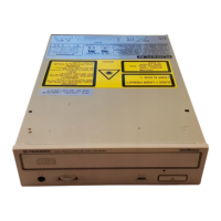
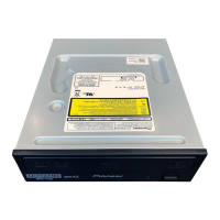
| Model | DR-2111 |
| Category | CD/CDR Drive |
| Language | English |