EasyManua.ls Logo

Pioneer DW-S114X User Manual

Pioneer DW-S114X
47 pages
To Next Page IconTo Next Page
Page #1 background imageLoading...
Page #1 background image
Service
Manual
CD-ROM
WRITER
DW-S114X
WY)
PIONEER’
The
Art
of
Entertainment
@
PIONEER
co-row
wniten
Ow.51100
°
"o
"0
“o”
ORDER
NO.
RRV1362
THIS
MANUAL
APPLICABLE
TO
THE
FOLLOWING
MODEL(S)
AND
TYPE(S).
Power
Requirement
a
$114X
TUCGM/WL|
=
©
—_|_AC100-240V
CONTENTS
1.
SAFETY
INFORMATION
-<
<1:
cceccceeceeeeeseeeseeeeeees
2.
EXPLODED
VIEWS,
PACKING
AND
PARTS
LIST
-s:-e:ceeceeeceeteeereeeees
3.
SCHEMATIC
AND
PCB
CONNECTION
DIAGRAMS:
--+--2+2-ss20
15
4.
PCB
PARTS
LIST
Ir
rrererererereee
err
ee
rere
rere
eee
37
PIONEER
ELECTRONIC
CORPORATION
4-1,
Meguro
1-Chome,
Meguro-ku,
Tokyo
153,
Japan
|
Automaticselect
=
|
Automaticselect
=
5.
ADJUSTMENTS
<eccerrecetcereeccesenseeenecesanenes
41
6.
DISASSEMBLY
«--ececceceeceeceeeeeceseeeeeeeseeseees
53
7.
IC
INFORMATION
<-ecescrecerceeceseeeeeceecerenenes
55
8.
BLOCK
DIAGRAMS
«-es-eseeceececcestteeeeese
eee ren
56
9.
PANEL
FACILITIES
---:-sceececeeeceseeseseeeeeeeeen
60
10.
SPECIFICATIONS
«sc-ccecescrecesceeeeseeeeseneaeeee
61
PIONEER
ELECTRONICS
SERVICE,
INC. P.O.
Box
1760,
Long
Beach,
CA
90801-1760,
U.S.A.
PIONEER
ELECTRONIC
(EUROPE)
N.V.
Haven
1087,
Keetberglaan
1,
9120
Melsele,
Belgium
PIONEER
ELECTRONICS
ASIACENTRE
PTE.
LTD.
501
Orchard
Road,
#10-00
Lane
Crawford
Place,
Singapore
0923
©
PIONEER
ELECTRONIC
CORPORATION
1995
T-IFY
JULY
1995
Printed
in
Japan
Question and Answer IconNeed help?

Do you have a question about the Pioneer DW-S114X and is the answer not in the manual?

Pioneer DW-S114X Specifications

General IconGeneral
BrandPioneer
ModelDW-S114X
CategoryCD/CDR Drive
LanguageEnglish

Summary

Safety Information

Safety Precautions

Essential safety checks for customer and technician protection.

Leakage Current Check

Procedure to measure leakage current to earth ground for safety.

Product Safety Notice

Information on special safety characteristics of replacement parts.

Laser Safety and Labels

Laser Warning Labels

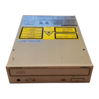
Identification and meaning of various caution labels on the product.

Additional Laser Safety Cautions

Specific warnings and interlock mechanisms related to laser safety.

Exploded Views, Packing and Parts List

Packing and Parts List

Details of product packing and the list of included parts.

Service Packing and Parts List

Packing and parts list for the servo mechanism assembly used in service.

Exterior Parts List

List of external components and their part numbers.

Mechanism Section Parts List

List of internal mechanism components and their part numbers.

Unit Parts Lists

Parts lists for various internal units like HAMP, CNTB, etc.

Servo Mechanism Assembly Parts List

Detailed parts list for the servo mechanism assembly.

Schematic and PCB Connection Diagrams

Overall Wiring Diagram

Comprehensive wiring diagram showing interconnections between major units.

HAMP and Pickup Assy PCB

Printed circuit board layout for the HAMP and Pickup assemblies.

HAMP Unit, Pickup, Sub Unit Schematics

Schematic diagrams for HAMP, Pickup, and Sub units.

Sub Unit Schematics

Detailed schematic diagrams for the Sub unit.

Main, CNTB, TOC, FG Board Schematics

Schematics for Main, CNTB, TOC, and FG boards.

Main and LDSB Unit Schematics

Schematic diagrams for the Main and LDSB units.

Main, LEDB, EJSB Unit Schematics

Schematic diagrams for Main, LEDB, and EJSB units.

Power Assy Schematic

Schematic diagram for the Power supply assembly.

Adjustments

VCO and Speed Control Adjustments

Procedure to optimize the VCO free-run frequency and slider speed control offset.

Laser Power Adjustments

Procedure to optimize the playback and recording laser diode power.

Focus and Tracking Adjustments

Adjustments for focus offset, mix ratio, and tracking error signals.

Servo Loop Gain and Offset Adjustments

Adjustments for servo loop gains and offset voltages.

Frequency Verification and Wobble Offset

Verification of VCO frequency and adjustment of wobble offset.

Disassembly

Front Panel Disassembly

Steps to remove the front panel of the unit.

Tray Section Disassembly

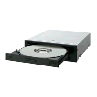
Steps to disassemble the tray section.

Servo Mechanism Assy Disassembly

Steps to remove the servo mechanism assembly.

Loading Mechanism Section Disassembly

Steps to disassemble the loading mechanism section.

IC Information

IC1008 (DYW1431) Information

Details on the IC1008 FLASH MEMORY ROM including pin arrangement and block diagram.

Block Diagrams

HAMP and Sub Units Block Diagram

Block diagram illustrating interconnections between HAMP and Sub units.

Main Unit Block Diagram

Block diagram detailing the functionality of the Main unit.

Panel Facilities

Front Panel Controls and Indicators

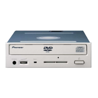
Description of front panel buttons, indicators, and disc tray.

Rear Panel Connectors and Switches

Description of rear panel SCSI connectors, function switches, and AC IN.

Power Cord Caution

Safety precautions for handling the power cord.

Specifications

General Specifications

General specifications for disc compatibility, data capacity, and speed.

Accessories and Power Details

List of accessories and power-related specifications like voltage and consumption.

Dimensions, Weight, and Environmental Specs

Physical dimensions, weight, and operating/storage environmental conditions.

Related product manuals