EasyManua.ls Logo

Pioneer DV-366-S User Manual

Pioneer DV-366-S
94 pages
To Next Page IconTo Next Page
Page #1 background imageLoading...
Page #1 background image
ORDER NO.
PIONEER CORPORATION 4-1, Meguro 1-chome, Meguro-ku, Tokyo 153-8654, Japan
PIONEER ELECTRONICS (USA) INC. P.O. Box 1760, Long Beach, CA 90801-1760, U.S.A.
PIONEER EUROPE NV Haven 1087, Keetberglaan 1, 9120 Melsele, Belgium
PIONEER ELECTRONICS ASIACENTRE PTE. LTD. 253 Alexandra Road, #04-01, Singapore 159936
PIONEER CORPORATION 2003
DV-366-S
RRV2755
DVD PLAYER
DV-366-S
THIS MANUAL IS APPLICABLE TO THE FOLLOWING MODEL(S) AND TYPE(S).
Model Type Power Requirement Region No.
Serial No.
Confirm 3rd & 4th
alphabetical letters.
DV-366-S RRXU AC110-127V/220-240V 4 &&PG######$$
DV-366-S RLXJ/NC
AC110-127V/220-240V
3 &&MP######$$
DV-366-S RDXJ/RB
AC110-127V/220-240V
2 &&MP######$$
DV-366-S BKXJ AC110V/220V 3 &&MP######$$
DV-366-S LFXJ AC110V 3 &&MP######$$
For details, refer to "Important symbols for good services".
T-ZZE MAY. 2003 printed in Japan
Question and Answer IconNeed help?

Do you have a question about the Pioneer DV-366-S and is the answer not in the manual?

Pioneer DV-366-S Specifications

General IconGeneral
BrandPioneer
ModelDV-366-S
CategoryDVD Player
LanguageEnglish

Summary

SAFETY INFORMATION

IMPORTANT SYMBOLS FOR GOOD SERVICES

PRODUCT SAFETY

Adherence to product regulations and safety instructions during servicing.

ADJUSTMENTS

Importance of adjustments for maintaining original performance and specifications.

SPECIFICATIONS

EXPLODED VIEWS AND PARTS LIST

BLOCK DIAGRAM AND SCHEMATIC DIAGRAM

BLOCK DIAGRAM

High-level overview of the system's functional blocks and data flow.

DVDM ASSY 1/3 [FRONT END BLOCK]

DVDM ASSY 2/3 [BACK END BLOCK]

DVDM ASSY 3/3 [AUDIO/VIDEO BLOCK]

POWER SUPPLY UNIT [VWR1366]

POWER SUPPLY UNIT [VWR1368]

PCB CONNECTION DIAGRAM

LOAB ASSY

Printed circuit board layout and connector pin assignments for the LOAB ASSY.

DVDM ASSY

Printed circuit board layout and connector pin assignments for the DVDM ASSY.

POWER SUPPLY UNIT PCB DIAGRAMS

POWER SUPPLY UNIT [VWR1366]

Printed circuit board layout for the VWR1366 power supply unit.

POWER SUPPLY UNIT [VWR1368]

Printed circuit board layout for the VWR1368 power supply unit.

PCB PARTS LIST

ADJUSTMENT

NECESSARY ADJUSTMENT POINTS

Outlines adjustment points required after replacing specific mechanical or PCB components.

TEST MODE OPERATIONS

TEST MODE PROCEDURES

Step-by-step guide on how to enter, set, play, and exit the test mode.

MECHANISM ADJUSTMENT

TANGENTIAL AND RADIAL HEIGHT COARSE ADJUSTMENT

Guide for performing the initial coarse adjustment of tangential and radial height.

DVD JITTER ADJUSTMENT

Steps to adjust the DVD jitter for optimal playback performance.

INITIALIZE FOCUS SWEEP SETTING

Procedure to set the focus sweep correctly after component replacement.

GENERAL INFORMATION

DIAGNOSIS AND SERVICE MODES

Covers test modes, shortcut keys, model info, service mode, error history, and ID settings.

DISASSEMBLY PROCEDURES

Step-by-step guide for disassembling the DVD player's main assemblies.

DISC AND CONTENT COMPATIBILITY

CLEANING PROCEDURES

PLAYER INTERFACE

REAR PANEL CONNECTIONS

Details the various output jacks and the AC IN connector on the rear panel.

REMOTE CONTROL FUNCTIONS

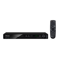
Detailed guide to all buttons and functions on the remote control unit.

Related product manuals