Do you have a question about the Pioneer DV-LX50 and is the answer not in the manual?
General guidelines for safe and proper repair procedures.
Technical specifications for laser diodes used in the device.
Ensures compliance with safety regulations and proper servicing environment.
Procedures for optimizing product performance and confirming specifications.
Guidelines for using correct lubricants, adhesives, and replacement parts.
Proper cleaning procedures for optical pickups, heads, and lenses.
Instructions for protecting the product during transit.
Guidelines for using lead-free solder and appropriate soldering iron techniques.
Procedures for safely removing and installing the DVD deck unit.
Steps to remove a disc when the unit has no power supply.
Procedure to cancel the stored 4-digit password in the Rating Level menu.
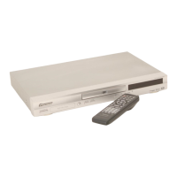
Lists all items included with the DVD player, such as remote control, cables, and batteries.
Details power requirements, consumption, weight, dimensions, and operating conditions.
Explains the pinout and function of the 21-pin AV connector.
Information about the HDMI output interface.
Details the output level and jack type for component video.
Information on S-Video output level and jack type.
Details the output level and jack type for standard video output.
Information on stereo audio output level, channels, and jacks.
Details compatible disc types like DVD, CD, Super VCD, and Fujicolor CD.
Information on playing DualDisc media, noting limitations with audio-only sides.
Specifies compatible CD-R/RW formats, multi-session, and unfinalized disc handling.
Details compatibility with DVD+R/+RW discs, focusing on video mode and finalization.
Outlines compatible DVD-R/-RW formats, including video recording (VR) mode.
Lists compatible compressed audio formats like MP3, WMA, and AAC, including bit-rates and DRM.
Explains MPEG-4 AAC audio coding, file formats, and DRM limitations.
Details WMA audio compatibility, compression technology, and licensing.
Describes DivX video technology, file naming conventions, and playback compatibility.
Specifies DivX Ultra Certified product features and playback enhancements.
Explains WMV video compression technology and player compatibility.
Details JPEG file compatibility, including formats, resolutions, and file extensions.
Discusses compatibility issues with discs created on PCs, including packet write mode.
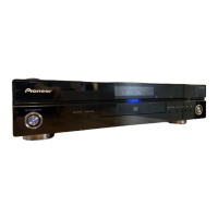
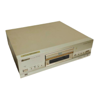
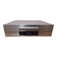
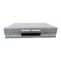
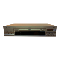
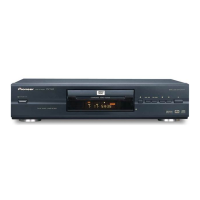
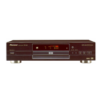
Identifies and describes the functions of the front panel buttons, display, and disc tray.
Details the function and connection types for each rear panel port.
Explains the meaning of each indicator light and character displayed on the unit.
Details the function of each button on the remote control unit.
Recommended checks to ensure product quality after repair.
Identifies the location of various PCB assemblies within the unit.
Lists special tools (jigs) required for diagnosis and operation checks.
Lists recommended lubricants, glues, and their part numbers for assembly.
Specifies cleaning tools and procedures for pickup lenses before shipping.
Provides a flowchart for diagnosing and resolving common power-on issues.
Lists symptoms associated with failures in specific ICs like EEPROM, Flash ROM, SDRAM, and DVD IC.
Method to diagnose laser diode degradation by measuring voltage on specific resistors.
Step-by-step guide on how to enter and exit the service mode for the unit.
Details on entering, releasing, and controlling laser diodes within the service mode.
Explains the meaning of address, code, status, and position indications in service mode.
Details the functions assigned to shortcut keys for memory clear, error rate measurement, and zoom.
Explains how error rates are displayed and calculated, and the meaning of indication plan contents.
Step-by-step instructions for disassembling the top cabinet, legs, and various PCBs.
Instructions for removing the DVD deck, rear jack PCB, DVD MT PCB, and audio PCB.
Steps for removing the disc tray, including unlocking supports.
Instructions for removing the traverse assembly, including screws and insulators.
Steps for removing the loading motor PCB, belt, and related components.
Instructions for removing rack loading, main gear, and pulley gear components.
Steps for removing the clamper assembly, plate clamper, and magnet clamper.
Instructions for removing the holder traverse and insulators (F/R).
Steps for removing switch PCB, gear middle, rack feed ass'y, and feed motor.
Guidelines for correctly folding and installing Flexible Flat Cables (FFCs).
Procedure for updating the unit's firmware to the latest version after PCB replacement.
Steps to interpret the firmware version code displayed on the unit.
Guidance on resolving problems if the firmware update fails or the disc is not recognized.
Illustrates the packaging components and lists their part numbers for identification.
Provides detailed part numbers for packing items and contrast table for model-specific accessories.
Shows an exploded view of the unit's exterior parts with numbered components.
Lists part numbers for exterior components and provides a contrast table for model variations.
Illustrates the DVD mecha assembly, identifying parts and grease application points.
Lists all components of the DVD mecha assembly with their respective part numbers.
Provides the schematic for the DVD MT PCB, focusing on MPEG/MICON interface.
Details the schematic for the DVD PCB, showing connections for video, audio, and regulators.
Shows the schematic related to memory components like FLASH and SDRAM on the DVD MT PCB.
Details the schematic for the DVD PCB, focusing on memory and interface connections.
Provides the schematic for the loader and motor driver circuits on the DVD MT PCB.
Details the schematic for the DVD PCB, focusing on motor driver circuits and related signals.
Shows the schematic related to digital audio interfaces and signal processing on the DVD MT PCB.
Details the schematic for the DVD PCB, illustrating digital audio signal paths and components.
Provides the schematic for the Video DAC circuit on the DVD MT PCB.
Details the schematic for the DVD PCB, illustrating video DAC signal paths and components.
Provides the schematic for the front left/right audio channels on the AUDIO PCB.
Details the schematic for the DVD PCB, showing 4-channel video switching functions.
Provides the schematic for the HDMI interface and related circuits on the DVD MT PCB.
Details the schematic for the DVD PCB, illustrating HDMI signal paths and connections.
Shows the schematic for CEC and Sub-Micon interface circuits on the DVD MT PCB.
Details the schematic for the DVD PCB, illustrating CEC and Sub-Micon signal paths.
Provides the schematic for the voltage regulator circuits on the DVD MT PCB.
Details the schematic for the DVD PCB, illustrating regulator circuits and power distribution.
Provides the schematic for the surround sound channels on the AUDIO PCB.
Provides the schematic for surround sound channels on the AUDIO PCB, including MUTE control.
Provides schematics for surround sound channels, including MUTE control and MP MODIFY functions.
Provides the schematic for the SCART connector and related video/audio signals.
Details the schematic for the SCART PCB, illustrating signal paths and components.
Provides schematics for the Operation 1, 2, and 3 PCB assemblies.
Details schematics for operation PCBs, including front panel control interface and LEDs.
Provides the schematic diagram for the power supply unit (PSU) of the device.
Details the schematic for the power PCB, illustrating power distribution and control circuits.
Displays oscilloscope waveforms for various signals like MPEG, Digital Audio, Memory, and Video DAC.
Shows oscilloscope waveforms for Video Driver, CES/Sub-Micon, and Display signals.
Displays waveforms measured from the Rear Jack PCB and Audio PCB assemblies.
Explains part number matching, symbol comparison, and viewing points for PCB diagrams.
Shows the component layout and placement on the Side A of the DVD MT PCB.
Shows the component layout and placement on the Side B of the DVD MT PCB.
Shows the component layout and placement on the Side A of the Audio PCB.
Shows the component layout and placement on the Side B of the Audio PCB.
Shows the component layouts for Operation 1, 2, 3, Rear Jack, and Power PCB assemblies.
Shows component layouts for Power and Operation PCBs on their Side B.
Illustrates the loading motor and switch assemblies, including component placement.
Lists major assemblies like PCB boards, DVD Mecha, and Semiconductors with their part numbers.
Lists individual components like resistors, capacitors, switches, and ICs with their part numbers.
Lists specific resistors used in the Power PCB assembly with their part numbers.
| DVD Player Type | DVD player |
|---|---|
| Progressive Scan | Yes |
| Audio DAC | 192 kHz/24-bit |
| HDMI Output | Yes |
| Component Video Output | Yes |
| S-Video Output | Yes |
| Composite Video Output | Yes |
| Digital Audio Output | Coaxial, Optical |
| Output Resolution | 480i, 480p, 720p, 1080i |
| Playable Formats | DVD-Video, DVD-R/RW, CD, CD-R/RW, MP3, JPEG |
| Analog Audio Output | 2 channel |