Do you have a question about the Pioneer DVH-755AV/XERD and is the answer not in the manual?
| Bluetooth | No |
|---|---|
| USB Port | Yes |
| AUX Input | Yes |
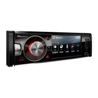
| Video Output | Yes |
| Remote Control | Yes |
| Audio Output Power | 50 W |
| Tuner | AM/FM |
| Supported Formats | MP3, WMA |
| Display | LCD |
| Playback | CD, USB |
| Amplifier | MOSFET |
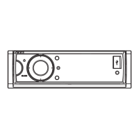
| Dimensions | 178 x 100 x 165 mm |
Essential safety guidelines for servicing personnel, including handling sharp edges and ICs.
Critical cautions regarding laser diode emission and eye protection during service.
Guidelines for conforming to regulations and maintaining product safety during service.
Illustrates the interconnections between major modules and boards.
Lists common error messages, their causes, and recommended actions for resolution.
Method for ejecting a stuck disc by rotating the mechanism's roller.
Method for ejecting a stuck disc by removing the unit's top cover.
Detailed schematic diagram for the Main Board Assembly (Part 1 of 2).
Detailed schematic diagram for the Main Board Assembly (Part 2 of 2).
Schematic diagram for the SB Ass'y, focusing on the power section.
Schematic diagram for the SB Ass'y, focusing on the main processing section.
Schematic diagrams for the Key Board (KB) and Auxiliary (AUX) Printed Circuit Boards.
Schematic diagrams for the CB and LB Ass'ys.