EasyManua.ls Logo

Pioneer DVR-220-S User Manual

Pioneer DVR-220-S
122 pages
To Next Page IconTo Next Page
Page #1 background imageLoading...
Page #1 background image
ORDER NO.
PIONEER CORPORATION 4-1, Meguro 1-chome, Meguro-ku, Tokyo 153-8654, Japan
PIONEER ELECTRONICS (USA) INC. P.O. Box 1760, Long Beach, CA 90801-1760, U.S.A.
PIONEER EUROPE NV Haven 1087, Keetberglaan 1, 9120 Melsele, Belgium
PIONEER ELECTRONICS ASIACENTRE PTE. LTD. 253 Alexandra Road, #04-01, Singapore 159936
PIONEER CORPORATION 2004
PULL-OPEN
STANDBY/ON
DISC
NAVIGATOR
DISC
HISTORY
OPEN/CLOSE REC
REC MODE
VIDEO/R/RW
DVR-220-S
RRV2925
DVD RECORDER
DVR-220-S
DVR-225-S
THIS MANUAL IS APPLICABLE TO THE FOLLOWING MODEL(S) AND TYPE(S).
Model Type Power Requirement Region No.
Serial No.
Please confirm 3rd & 4th
alphabetical letters.
DVR-220-S KU/CA AC120V 1
DVR-220-S KUXU/CA AC120V 1 &&PG######$$
DVR-220-S KUXQ/CA AC120V 1 &&CP######$$
DVR-225-S KUXU/CA AC120V 1 &&PG######$$
÷ When servicing this model, some service procedures may reset the settings that customer
set (*) to the factory default settings. Make sure to explain this to the customer.
(*) : Initial Setup (Clock Setting, Remote Control Set, Channel settings, Video Out settings,
Audio In settings, Audio Out settings, Language settings)
Refer to the chapter 12 of the Operating Instructions for more details.
For details, refer to "Important symbols for good services" .
T-ZZV APR. 2004 printed in Japan

Other manuals for Pioneer DVR-220-S

Question and Answer IconNeed help?

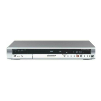
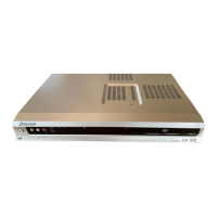
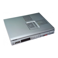
Do you have a question about the Pioneer DVR-220-S and is the answer not in the manual?

Pioneer DVR-220-S Specifications

General IconGeneral
TypeDVD Recorder
Recording FormatsDVD-R, DVD-RW, DVD+R, DVD+RW
Video Recording FormatMPEG-2
Audio Recording FormatDolby Digital
Hard DriveNo
Video OutputComposite, S-Video, Component
Progressive ScanYes
USB PortNo
Playback FormatsDVD-Video, DVD-R, DVD-RW, DVD+R, DVD+RW, CD-R, CD-RW
Disc CompatibilityDVD-R, DVD-RW, DVD+R, DVD+RW, CD-R, CD-RW
TunerNTSC
InputsComposite, S-Video
OutputsComposite, S-Video, Component

Summary

Safety Information

Safety Precautions and Notices

General safety precautions, warnings, and notices for service technicians.

Specifications

Input/Output Specifications

Details of various input and output terminals and their signal levels.

Exploded Views and Parts List

Front Panel Diagram and Parts

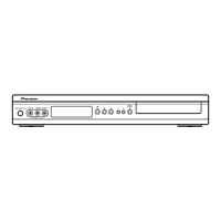
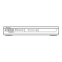
Exploded view of the front panel components and its parts list.

Block Diagrams and Schematic Diagrams

Overall Block Diagram

Overall system block diagram showing signal flow between major units.

TUNB and FRJB ASSYS Block Diagram

Block diagrams for the TUNB, JCKB, and FRJB ASSYS.

MAIN ASSY Block Diagram

Block diagram detailing the functions within the MAIN ASSY.

Power Block Diagram

Block diagram illustrating the power distribution to various ASSYs.

Overall Wiring Diagram

TUNB ASSY Wiring Diagram

Wiring diagram for the TUNB ASSY.

JCKB ASSY Wiring Diagram

Wiring diagram for the JCKB ASSY.

MAIN ASSY Wiring Diagram

Wiring diagram for the MAIN ASSY.

POWER SUPPLY UNIT Wiring Diagram

Wiring diagram for the POWER SUPPLY UNIT.

TUNB ASSY Schematics

TUNB ASSY Schematic

Detailed schematic diagram of the TUNB ASSY.

JCKB ASSY Schematics

JCKB ASSY (1/2) Schematic

Schematic diagram for the JCKB ASSY (part 1/2).

JCKB ASSY (2/2) Schematic

Schematic diagram for the JCKB ASSY (part 2/2).

MAIN ASSY Schematics

MAIN ASSY (1/4) Schematic

Schematic diagram for the MAIN ASSY (part 1/4).

MAIN ASSY (2/4) Schematic

Schematic diagram for the MAIN ASSY (part 2/4).

MAIN ASSY (3/4) Schematic

Schematic diagram for the MAIN ASSY (part 3/4).

MAIN ASSY (4/4) Schematic

Schematic diagram for the MAIN ASSY (part 4/4).

ASSYS Schematics

FLKY ASSY Schematic

Schematic diagram for the FLKY ASSY.

KIRB ASSY Schematic

Schematic diagram for the KIRB ASSY.

FRJB ASSY Schematic

Schematic diagram for the FRJB ASSY.

Power Supply Unit Schematic

Power Supply Unit Schematic

Schematic diagram of the Power Supply Unit.

Wave Forms

MAIN ASSY Wave Forms

Waveforms for test points in the MAIN ASSY.

PCB Parts Lists

Adjustment Procedures

TUNB ASSY Adjustment

Procedures for adjusting the TUNB ASSY.

MAIN ASSY Adjustment

Adjustment procedures for the MAIN ASSY.

General Information and Diagnosis

Setup Sequence Diagram

Flowchart illustrating the setup sequence for the unit.

Disassembly Procedures

Component Disassembly and Diagnosis

DRIVE Assy R7R Disassembly

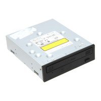
Steps for disassembling the DRIVE Assy R7R.

MAIN Assy Disassembly

Steps for disassembling the MAIN Assy.

Diagnosis Procedure

Diagnosis steps involving an insulation sheet and unit arrangement.

Disc and Content Format Compatibility

Remote Control Operations

Related product manuals