ORDER NO.
PIONEER CORPORATION 4-1, Meguro 1-chome, Meguro-ku, Tokyo 153-8654, Japan
PIONEER ELECTRONICS (USA) INC. P.O. Box 1760, Long Beach, CA 90801-1760, U.S.A.
PIONEER EUROPE NV Haven 1087, Keetberglaan 1, 9120 Melsele, Belgium
PIONEER ELECTRONICS ASIACENTRE PTE. LTD. 253 Alexandra Road, #04-01, Singapore 159936
PIONEER CORPORATION 2004
FH-M8047ZT/XN/ES
CRT3254
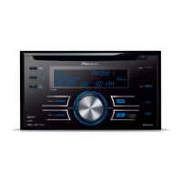
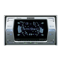
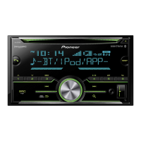
HEAD UNIT
FH-M8047
ZT
/XN/ES
FH-M8047
ZT
/XIN/ES
FH-M8147
ZT
/XN/ES
FH-M8147
ZT
/XIN/ES
This service manual should be used together with the following manual(s):
Model No. Order No. Mech.Module Remarks
CX-3057 CRT3026 S10MP3 CD Mech. Module:Circuit Description, Mech. Description, Disassembly
CX-1011 CRT2406 3L CD Mech. Module:Mech. Description, Disassembly
VEHICLE DESTINATION
PRODUCED
AFTER
OEM PARTS No. ID No. PIONEER MODEL No.
INDONESIA APRIL 2005 86120-0K140 P7836 FH-M8047ZT/XN/ES
INDONESIA
AUGUST 2004 86120-0K120 P7832
FH-M8047ZT/XIN/ES
GULF COOPERATION COUNCIL JULY 2005 86120-0K100 P7837 FH-M8147ZT/XN/ES
GULF COOPERATION COUNCIL JULY 2005
86120-0K060 P7833
FH-M8147ZT/XIN/ES
For details, refer to "Important symbols for good services".
K-ZZD.JUNE 2004 printed in Japan
Dolby noise reduction manufactured under license from Dolby Laboratories Licensing
Corporation.
"Dolby" and the double-D symbol are trademarks of Dolby Laboratories Licensing Corpo-
ration.
TOYOTA



 Loading...