EasyManua.ls Logo

Pioneer FH-P404 UC User Manual

Pioneer FH-P404 UC
92 pages
To Next Page IconTo Next Page
Page #1 background imageLoading...
Page #1 background image
MULTI-CD/MD CONTROL TUNER CD DECK AMPLIFIER
FH-P404 UC
Se
r
v
i
c
e
M
a
nu
a
l
FH-P404 ES
FH-P404/UC
PGM
ATT
DISPLAY CLOCK
ESC
BAND
AUDIO
TRK
/
SEEK DISC
/
CH
FUNCTION
SEL
DIRECT EQ
VOLUME
OFF
SOURCE
AF
D
S/A
165432
P
CD
EJECT
HIGH POWER 40Wx4
CD TUNER DECK AMPFH-P404
EJECT
AUTOMATIC CASSETTE LOADING & EJECTION
DOLBY B NR
PIONEER ELECTRONIC CORPORATION 4-1, Meguro 1-Chome, Meguro-ku, Tokyo 153-8654, Japan
PIONEER ELECTRONICS SERVICE INC. P.O.Box 1760, Long Beach, CA 90801-1760 U.S.A.
PIONEER ELECTRONIC [EUROPE] N.V. Haven 1087 Keetberglaan 1, 9120 Melsele, Belgium
PIONEER ELECTRONICS ASIACENTRE PTE.LTD. 501 Orchard Road, #10-00, Lane Wheelock Place, Singapore 23880
C PIONEER ELECTRONIC CORPORATION 1998
ORDER NO.
CRT2247
CONTENTS
1. SAFETY INFORMATION ............................................2
2. EXPLODED VIEWS AND PARTS LIST.......................3
3. SCHEMATIC DIAGRAM ...........................................12
4. PCB CONNECTION DIAGRAM ................................38
5. ELECTRICAL PARTS LIST ........................................52
6. ADJUSTMENT..........................................................62
7. GENERAL INFORMATION .......................................68
7.1 PARTS .................................................................68
7.1.1 IC................................................................68
7.1.2 DISPLAY....................................................75
7.2 DISASSEMBLY ...................................................79
7.3 BLOCK DIAGRAM ..............................................80
8. OPERATIONS AND SPECIFICATIONS.....................82
- See the separate manual CX-597(CRT1829) for the CD mechanism description, disassembly and circuit
description.
- The CD mechanism employed in this model is one of S7 series.
- See the separate manual CX-631(CRT1640) for the cassette mechanism description, disassembly and
circuit description.
- The cassette mechanism employed in this model is one of 2L series.
- Dolby noise reduction manufactured under license from Dolby Laboratories Licensing Corporation.
"Dolby" and the double-D symbol are trademarks of Dolby Laboratories Licensing Corporation.
K-ZZB. AUG. 1998 Printed in Japan
w
w
w
.
x
i
a
o
y
u
1
6
3
.
c
o
m
Q
Q
3
7
6
3
1
5
1
5
0
9
9
2
8
9
4
2
9
8
T
E
L
1
3
9
4
2
2
9
6
5
1
3
9
9
2
8
9
4
2
9
8
0
5
1
5
1
3
6
7
3
Q
Q
TEL 13942296513 QQ 376315150 892498299
http://www.xiaoyu163.com
Question and Answer IconNeed help?

Do you have a question about the Pioneer FH-P404 UC and is the answer not in the manual?

Pioneer FH-P404 UC Specifications

General IconGeneral
BrandPioneer
ModelFH-P404 UC
CategoryAmplifier
LanguageEnglish

Summary

CONTENTS

SAFETY INFORMATION

Essential safety precautions for handling and repair.

EXPLODED VIEWS AND PARTS LIST

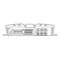
Visual breakdown and list of all components for easy identification.

PACKING

Details regarding product packaging and included items.

EXTERIOR

EXTERIOR SECTION PARTS LIST

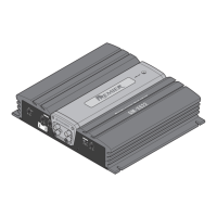
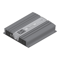
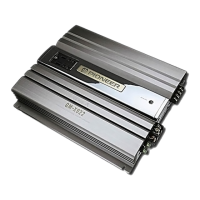
List of parts specifically for the exterior assembly.

CD MECHANISM MODULE

CD MECHANISM MODULE SECTION PARTS LIST

Parts specific to the CD mechanism module.

CASSETTE MECHANISM MODULE

CASSETTE MECHANISM MODULE SECTION PARTS LIST

Parts specific to the cassette mechanism module.

SCHEMATIC DIAGRAM

OVERALL CONNECTION DIAGRAM(GUIDE PAGE)

Guide to understanding the main schematic connections.

FM/AM TUNER UNIT

Schematic for the FM/AM tuner section.

TUNER DECK AMP UNIT

Schematic for the tuner deck amplifier section.

DD CONVERTER UNIT

DECK UNIT

SWITCH UNIT, FL UNIT

PCB CONNECTION DIAGRAM

TUNER DECK AMP UNIT

PCB layout and component placement for the tuner deck.

ELECTRICAL PARTS LIST

MISCELLANEOUS

List of miscellaneous electrical components.

CAPACITORS

List of all capacitor parts used in the unit.

RESISTORS

List of all resistor parts used in the unit.

ADJUSTMENT

TUNER ADJUSTMENT

Step-by-step guide for adjusting the tuner section.

FM ADJUSTMENT

DOLBY B NR ADJUSTMENT

Procedure for adjusting Dolby B noise reduction.

CD SECTION

Precautions

Important safety and operational precautions for the CD section.

CHECKING THE GRATING AFTER CHANGING THE PICKUP UNIT

GENERAL INFORMATION

PARTS

General overview of parts, including IC pin functions.

DISASSEMBLY

Removing the Case

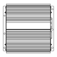
Instructions for removing the main unit case.

Removing the CD Mechanism Module

Instructions for removing the CD mechanism module.

Removing the Cassette Mechanism Module

Instructions for removing the cassette mechanism module.

BLOCK DIAGRAM

OPERATIONS AND SPECIFICATIONS

OPERATIONS

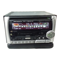
General operating procedures for the unit.

SPECIFICATIONS

Related product manuals