EasyManua.ls Logo

Pioneer GM-DX871/XEVUC User Manual

Pioneer GM-DX871/XEVUC
18 pages
To Next Page IconTo Next Page
Page #1 background imageLoading...
Page #1 background image
ORDER NO.
PIONEER CORPORATION 28-8, Honkomagome 2-chome, Bunkyo-ku, Tokyo 113-0021, Japan
PIONEER ELECTRONICS (USA) INC. P.O. Box 1760, Long Beach, CA 90801-1760, U.S.A.
PIONEER EUROPE NV Haven 1087, Keetberglaan 1, 9120 Melsele, Belgium
PIONEER ELECTRONICS ASIACENTRE PTE. LTD. 2 Jalan Kilang Barat, #07-01, Singapore 159346
PIONEER CORPORATION 2019
GM-D8701/XEVUC
CRT6387
CLASS D MONO AMPLIFIER
GM-D8701
/XEVUC
GM-DX871/XEVUC
GM-D8701/XEVEW5
GM-D8701/XEVES
K-ZZZ JAN. 2019
Question and Answer IconNeed help?

Do you have a question about the Pioneer GM-DX871/XEVUC and is the answer not in the manual?

Pioneer GM-DX871/XEVUC Specifications

General IconGeneral
Channels1
ClassD
Signal-to-Noise Ratio100 dB
Frequency Response10Hz - 240Hz
Operating Voltage14.4V (11V - 16V allowable)

Summary

1. SERVICE PRECAUTIONS

1.1 SAFETY PRECAUTIONS

General safety guidelines to follow during service operations.

1.2 NOTES ON DISASSEMBLY / ASSEMBLY

Important notes regarding the safe disassembly and reassembly of the unit.

1.3 NOTES ON REPLACING PARTS

Precautions for replacing components, emphasizing static discharge protection.

2. SPECIFICATIONS

2.1 SPECIFICATIONS

Provides the main technical data and parameters for the device.

3. BASIC ITEMS FOR SERVICE

3.1 CHECK POINTS AFTER SERVICING

Essential checks to ensure product quality and customer satisfaction post-service.

3.2 JIGS LIST

Lists specific jigs and lubricants required for maintenance and repair.

5. DIAGNOSIS

5.1 CONNECTOR FUNCTION DESCRIPTION

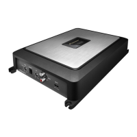
Details the function and location of various connectors on the unit.

9. EXPLODED VIEWS AND PARTS LIST

9.1 PACKING SECTION

Exploded view and parts list specific to the packing and shipping components.

10. SCHEMATIC DIAGRAM

10.1 P.C.B TOTAL ASSY

Schematic representation of the entire Printed Circuit Board assembly.

11.PCB CONNECTION DIAGRAM

11.1 P.C.B TOTAL ASSY

Layout and connection details for the main Printed Circuit Board.

Related product manuals