EasyManua.ls Logo

Pioneer HTP102-SW - User Manual

Pioneer HTP102-SW
2 pages
Print Icon
To Next Page IconTo Next Page
Loading...
1
HTP102-SW
Service
Manual
ORDER NO.
PET98005
PIONEER ELECTRONIC CORPORATION 4-1, Meguro 1-Chome, Meguro-ku, Tokyo 153-8654, Japan
PIONEER ELECTRONICS SERVICE, INC. P.O. Box 1760, Long Beach, CA 90801-1760, U.S.A.
PIONEER ELECTRONIC (EUROPE) N.V. Haven 1087, Keetberglaan 1 B-9120 Melsele, Belgium
PIONEER ELECTRONICS ASIACENTRE PTE. LTD. 501 Orchard Road, #10-00, Wheelock Place, Singapore 238880
©PIONEER ELECTRONIC CORPORATION 1998 1998 Printed in U.S.A.
Place unit upside-down on a soft cloth so as not to scratch the
top panel.
The woofer is attached to the baffle by 4 screws. To detach the
woofer, unfasten those screws and lift up. Detach the speaker
wires by gently pulling the connectors off the speakers’ binding
posts. When attaching the woofer, push the connectors on to
the binding posts and attach the speaker to the baffle by
tightening the screws.
Once the woofer has been removed, the terminal cup may be
removed by unfastening the six screws that fasten it to the
backboard. Note: Do not pull on wires at the terminal side if
not disconnected from the woofer as this may result in damage
to the binding posts, wires, or connectors. To attach, re-fasten
the screws on to the backboard making certain that the text on
the terminal cup is oriented in the correct direction.
The cosmetic duct is attached to the cabinet by application of
adhesives. To detach, first remove woofer as described above.
From within the cabinet, rock the port tube back and forth until
the assembly comes loose. To attach, press-fit the inside and
outside port rings on to the port tube and apply hot melt
adhesive around the circumference of outside port ring and
press fit on to the front board.
The foot may be detached by removing one external screw. To
attach, refasten foot with screw.
HOW TO REASSEMBLE AND
DISASSEMBLE
65S
This service manual is intended for qualified service technicians; it is not
meant for the casual do-it- your selfer. Qualified technicians have the
necessary test equipment and tools, and have been trained to properly and
safely repair complex products such as those covered by this manual.
Improperly performed repairs can adversely affect the safety and reliability
of the product and may void the warranty. If you are not qualified to
perform the repair of this product properly and safely, you should not risk
trying to do so and refer the repair to a qualified service technician.
WARNING
THIS PRODUCT CONTAINS LEAD IN SOLDER AND CERTAIN
ELECTRICAL PARTS CONTAIN CHEMICALS WHICH ARE
KNOWN TO THE STATE OF CALIFORNIA TO CAUSE CANCER,
BIRTH DEFECTS OR OTHER REPRODUCTIVE HARM.
Health & Safety Code Section 25249.6 - Proposition 65
SPEAKER SYSTEM
HTP102-SW
Question and Answer IconNeed help?

Do you have a question about the Pioneer HTP102-SW and is the answer not in the manual?

Overview

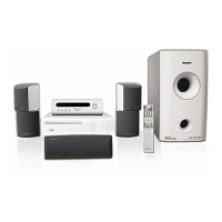
This document is a service manual for the Pioneer HTP102-SW Speaker System, a subwoofer designed to enhance the audio experience by reproducing low-frequency sounds. It provides essential information for qualified service technicians regarding the device's components, assembly, disassembly, and maintenance.

Function Description

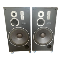
The HTP102-SW is a dedicated subwoofer, part of a larger speaker system, designed to handle the low-frequency audio spectrum. It features a low-frequency transducer (woofer) responsible for producing deep bass sounds, thereby enriching the overall sound quality of a home entertainment setup. The system includes a port tube, which is a common design element in bass-reflex enclosures, used to improve bass response and efficiency. The terminal cup, equipped with a network, serves as the interface for connecting the subwoofer to an audio source and potentially to other speakers in the system. The inclusion of speaker wires (dark blue and red, 10', 18 GA) suggests it is designed for passive operation, requiring an external amplifier or receiver to power it.

Important Technical Specifications

While specific power ratings or frequency response ranges are not explicitly detailed in this excerpt, the manual does list key components that provide insight into its technical makeup:

  • Low Frequency Transducer: Model 20-207A/XL. This is the primary driver responsible for bass reproduction.
  • Port Tube: Composed of a Paper Port Tube (255136), Front Port Ring (Plastic) (254306), and Rear Port Ring (Plastic) (254346). This indicates a bass-reflex design, which typically enhances low-frequency output.
  • Terminal with Network: Model 255121. This component likely includes a crossover network to filter frequencies, ensuring that only the appropriate low frequencies are sent to the woofer. The schematic diagram shows Polyswitch RXE135 and 6.0 mH inductors, which are components typically found in crossover networks for speaker protection and frequency shaping.
  • Speaker Wires: Provided in two colors (Dark Blue and Red) and specifications (10 feet, 18 gauge), indicating standard wiring for audio connections.
  • Connectors: The schematic diagram shows #205 FEMALE, RED and #110 FEMALE, BLACK connectors, which are standard spade or quick-disconnect terminals for speaker connections.

Usage Features

The HTP102-SW is designed to be an integral part of a home theater or audio system. Its primary usage is to augment the bass output of other speakers, providing a more immersive and impactful audio experience, particularly for movies and music with significant low-frequency content. The presence of "OUTPUT TO FRONT SPK.(L) TERMINAL CUP" and "OUTPUT TO FRONT SPK.(R) TERMINAL CUP" in the schematic suggests that the subwoofer might incorporate a pass-through or high-level input/output feature, allowing it to be connected in-line with main stereo speakers, with the subwoofer handling the low frequencies and passing higher frequencies to the main speakers. This is a common feature in subwoofers that do not have dedicated LFE (Low-Frequency Effects) inputs. The "Foot w/Non-Skid Pad" (250111) indicates attention to stability and vibration dampening, ensuring the subwoofer remains in place and minimizes unwanted resonances during operation.

Maintenance Features

The manual provides detailed instructions for disassembly and reassembly, which are crucial for maintenance and repair:

  • Woofer Removal: The woofer is secured by 4 screws and can be detached by unfastening these screws and gently pulling off the speaker wire connectors from the binding posts. This allows for inspection or replacement of the woofer.
  • Terminal Cup Removal: After the woofer is removed, the terminal cup can be accessed and detached by unfastening six screws from the backboard. A warning is given not to pull on wires at the terminal side if not disconnected from the woofer, to prevent damage to binding posts, wires, or connectors. This facilitates access to the internal crossover network or wiring.
  • Cosmetic Duct (Port Tube) Removal: The port tube is attached with adhesives. To detach, the woofer must first be removed, and then the port tube can be rocked back and forth from within the cabinet until it comes loose. Reassembly involves press-fitting the port rings and applying hot melt adhesive.
  • Foot Detachment: The foot is attached by a single external screw, making it easy to remove or reattach.

The manual emphasizes that these procedures are for "qualified service technicians" due to the complexity and potential safety implications of improper repairs. It also highlights the importance of using "parts of identical designation" for replacement, especially for components marked with a "mark," which indicates a critical safety factor. A "WARNING" regarding lead in solder and certain electrical parts containing chemicals known to cause cancer, birth defects, or other reproductive harm (Proposition 65) is included, underscoring the need for proper handling and disposal during maintenance. The detailed parts list, including screws, rings, and wires, ensures that technicians have the necessary information for ordering and replacing components. The schematic diagram further aids in troubleshooting and understanding the internal wiring and component connections.

Pioneer HTP102-SW Specifications

General IconGeneral
BrandPioneer
ModelHTP102-SW
CategorySpeaker System
LanguageEnglish

Related product manuals