EasyManua.ls Logo

Pioneer KE-5100 User Manual

Pioneer KE-5100
33 pages
To Next Page IconTo Next Page
Page #1 background imageLoading...
Page #1 background image
Mi
The
photo
shows
the
mode!
KE-6100.
ORDER
NO.
CRT
—245-0
CASSETTE
CAR
STEREO
WITH
AM/FM
ELECTRONIC
TUNER
E-5100
US,
CA
CASSETTE
CAR
STEREO
WITH
AM/FM
ELECTRONIC
TUNER
Subject:
KE-5100
E-6100
US,
CA
For
Cassette
Mechanism,
refer
to
the
Service
Manual
of
unit
number
CX-100A/P.
KE-6100
For
Cassette
Mechanism,
refer
to
the
Service
Manual
of
unit
number
CX-100A/N.
.
*
‘Dolby’
and
the
double-D
symbol
are
trademarks
of
Dolby
Laboratories
Licensing
Corporation.
¢
Noise
Reduction
System
manufactured
under
license
from
Dolby
Laboratories
Licensing
Corporation.
SPECIFICATIONS
General
Power
source
...........
DC14.4V
(10.8
~
15.6V
allowable)
Grounding
sySteM..
2...
ce
eee
Negative
type
Dimensions
(chassis)
.........
180(W)
x
50(H)
x
150(D)
mm
(7-1/8(W)
x
2(H)
x
5-7/8(D)
in.)
(nose)
.........005
105(W)
x
45(H)
x
30(D)
mm
(4-1/8(W)
x
1-3/4(H)
x
1-1/8(D)
in.)
Shaft
interval.
..2.....0.
0.0000
cee
eee
147
mm
(5-3/4
in.)
WIG
M
tie
secrete
08
5
lates
sale
we
ata
Soba
se
les wre
ees
1.7
kg
(3.7
Ibs.)
Amplifier
Continuous
power
output
is
2.9W
per
channel
min.
into
4
ohms,
both
channels
driven
50
to
15,000
Hz
with
no
more
than
5%
THD.
Maximum
power
output........
0.00.20
ee
eee
6W
+
6W
Load
impedance...............005.
40
(4~
80
allowable)
Loudness
contour........
+
12
dB
(100
Hz),
+4dB
(10
kHz)
Tape
Player
(volume:
—30
dB)
TADG
i,6
sched
4
Wee
sees
Compact
cassette
tape
(C-30
~
C-90)
Tape'speeds:.
cviic
eas
cvcteacee
a
oa
au ee
eee
4.76
cm/sec.
(+0.19
cm/sec.
—0.05
cm/sec.)
Fast
forward/rewind
time
.........
Within
100
sec.
for
C-60
Wow
&
flutter.............
No
more
than
0.15%
(WRMS)
Frequency
response
Bo
emg
ehatae
Le
50
~
16,000
Hz
(+3
dB)
(at
metal)
(KE-6100)
50
~
12,000
Hz
(+3
dB)
Stereo
separation
.........
0.
cee
eee
eee
More
than
45
dB
Signal-to-noise
ratio
5.
Md
Aut
gard
meta
deat
Dolby
NR
IN:
More
than
60
dB
(KE-6100)
(IHF-A
network,
at
1W)
Dolby
NR
OUT:
More
than
52
dB
(KE-5100/6100)
(IHF-A
network,
at
1W)
FM
Tuner
Frequency
range
...........0
cence
eens
87.9~
107.9
MHz
Usable
sensitivity
............
16.8
dBf
(1.9nV/752,
mono)
50
dB
quieting
sensitivity.......
19.2
dBf
(2.54V/752,
mono)
Alternate
channel
selectivity............
70
dB
(
+
400
kHz)
Distortion
............000-
0.3%
(at
65
dBf,
1
kHz,
stereo)
Frequency
response
..............
50
~
12,000
Hz
(+3
dB)
Stereo
separation............005.
40
dB
(at
65
dBf,
1
kHz)
AM
Tuner
Frequency
range...
.....
cece
eee
eee
530
~
1,620
kHz
Usable
sensitivity
............
30nV
(29.5
dB)
(S/N:
20
dB)
Selectivity...
0.0...
cece
eee
eee
eee
eee
DO
GB
(+
10
kHz)
These
specifications
were
determined
and
are
presented
in
ac-
cordance
with
specification
standards
established
by
the
Ad
Hoc
Committee
of
Car
Stereo
Manufacturers.
Note:
Specifications
and
the
design
are
subject
to
possible
modifica-
tion
without
notice
due
to
improvements.
PIONEER
ELECTRONIC
CORPORATION
-2-1,
Meguro
1-Chome,
Meguro-ku,
Tokyo
153,
Japen
PIONEER
ELECTRONICS
OF
AMERICA
1925
&.
Dominguez
St.
Long
Seach,
Calif.
90810
PIONEER
ELECTRONIC
(EUROPE)
N.V.
Luithagen-Haven
9,
2030
Antwerp,
Belgium
PIONEER
ELECTRONICS
AUSTRALIA
PTY.
LTD.
178-184
Boundary
Road,
Braeside,
Victoria
3195,
Australia
EK
©
FEB.
1981
Printed
in
Japan
Question and Answer IconNeed help?

Do you have a question about the Pioneer KE-5100 and is the answer not in the manual?

Pioneer KE-5100 Specifications

General IconGeneral
BrandPioneer
ModelKE-5100
CategoryCar Receiver
LanguageEnglish

Summary

SPECIFICATIONS

General

Basic operating parameters and physical specifications of the unit.

Amplifier

Technical details of the audio amplification stage.

FM Tuner

Specifications for FM radio reception performance.

AM Tuner

Specifications for AM radio reception performance.

1. PARTS LOCATION

Component Identification

Visual labels for major internal units and parts.

2. CIRCUIT DESCRIPTION

Block Diagram Overview

High-level functional representation of the unit's circuitry.

Level Diagram

Illustrates signal amplitude levels across various circuit stages.

2.1 TAPE SECTION

Equalizer Amplifier

Explains the circuit for equalizing tape playback characteristics.

Tape Selector Circuit

Details the mechanism for adapting to different tape types.

Dolby NR Circuit

Describes the operation of the Dolby noise reduction system.

2.2 TUNER SECTION

Front End

Covers the initial RF amplification and tuning stages.

IF Amplifier, Detector Circuit

Explains intermediate frequency amplification and signal detection.

Pulse Noise Suppressor (PNS)

Details the circuit for reducing pulse noise interference.

MPX Decoder

Explains the stereo signal decoding and separation circuitry.

Low-Pass Filter (LPF)

Describes the filter to remove FM pilot and subcarrier frequencies.

AM Tuner

Covers the design and function of the AM reception circuitry.

Regulator

Details the power supply regulation for tuner circuits.

2.3 MUTING CONTROL CIRCUIT

Muting Function Logic

Explains the conditions that trigger audio muting.

2.4 FUNCTIONS OF PD7003 CONTROL IC

PLL Section Operation

Describes the Phase-Locked Loop for FM tuning control.

Display Control Section

Explains how the unit's display segments are driven.

Switch Matrix Function

Details how front panel switches interact with the control IC.

Scan Operation Logic

Explains the automatic station scanning and stopping mechanism.

DC-DC Converter Operation

Describes the circuit for generating internal voltages from the battery.

3. ADJUSTMENT

3.1 CRYSTAL OSCILLATOR FREQUENCY ADJUSTMENT

Procedure for tuning the AM band crystal oscillator.

3.2 FM IF ADJUSTMENT

Procedure for aligning the FM Intermediate Frequency stages.

3.6 FM SCAN (SEEK) SENSITIVITY ADJUSTMENT

Procedure to set station seeking sensitivity levels.

3.3 FM TRACKING ADJUSTMENT

Procedure for aligning FM tuner response across frequencies.

3.4 FM MPX ADJUSTMENT

Procedure for optimizing stereo signal separation.

3.5 FM ARC ADJUSTMENT

Procedure for setting Automatic Reception Control levels.

3.7 AM IF ADJUSTMENT

Procedure for aligning AM Intermediate Frequency stages.

3.8 AM TRACKING ADJUSTMENT

Procedure for aligning AM tuner response across frequencies.

3.9 AM SCAN (SEEK) SENSITIVITY ADJUSTMENT

Procedure to set AM station seeking sensitivity levels.

3.10 DOLBY NR ADJUSTMENT

Procedure for setting Dolby NR circuit input/output levels.

3.11 DOLBY NR LEVEL ADJUSTMENT

Procedure for fine-tuning Dolby NR playback levels.
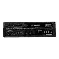
• IC's and Transistors

4. SCHEMATIC CIRCUIT DIAGRAM (KE-5100)

5. CONNECTION DIAGRAM (KE-5100)

6. CONNECTION DIAGRAM (KE-6100)

7. SCHEMATIC CIRCUIT DIAGRAM (KE-6100)

8. CABINET EXPLODED VIEW

9. CHASSIS EXPLODED VIEW

10. PACKING METHOD

11. ELECTRICAL PARTS LIST

Related product manuals