EasyManua.ls Logo

Pioneer KEH-P2033XM User Manual

Pioneer KEH-P2033XM
40 pages
To Next Page IconTo Next Page
Page #1 background imageLoading...
Page #1 background image
PIONEER CORPORATION 4-1, Meguro 1-Chome, Meguro-ku, Tokyo 153-8654, Japan
PIONEER ELECTRONICS (USA) INC. P.O.Box 1760, Long Beach, CA 90801-1760 U.S.A.
PIONEER EUROPE NV Haven 1087 Keetberglaan 1, 9120 Melsele, Belgium
PIONEER ELECTRONICS ASIACENTRE PTE.LTD. 253 Alexandra Road, #04-01, Singapore 159936
C PIONEER CORPORATION 2002
K-ZZS. NOV. 2002 Printed in Japan
ORDER NO.
CRT2979
MULTI-CD CONTROL HIGH POWER CASSETTE PLAYER WITH RDS TUNER
KEH-P2033RXM/EW
Service
Manual
BANDBAND
BASS/TREBLE BOOSTERBASS/TREBLE BOOSTER
3
6
2
5
1
4
KEH-P2033R
KEH-P2033R/XM/EW
KEH-P2030R
XM/EW
For details, refer to "Important symbols for good services".
- This service manual does not describe the CD test mode.
For the operations in the CD test mode, refer to the CD player's Service manual.
CONTENTS
SAFETY INFORMATION ............................................2
1. SPECIFICATIONS........................................................3
2. EXPLODED VIEWS AND PARTS LIST.......................4
2.1 PACKING...............................................................4
2.2 EXTERIOR .............................................................6
2.3 CASSETTE MECHANISM ....................................8
3. BLOCK DIAGRAM AND SCHEMATIC DIAGRAM ...10
3.1 BLOCK DIAGRAM ..............................................10
3.2 OVERALL CONNECTION DIAGRAM.................12
3.3 KEYBOARD UNIT ...............................................14
3.4 CASSETTE MECHANISM ..................................16
4. PCB CONNECTION DIAGRAM ................................18
4.1 TUNER AMP UNIT .............................................18
4.2 KEYBOARD UNIT ..............................................22
4.3 CASSETTE MECHANISM ..................................24
5. ELECTRICAL PARTS LIST ........................................25
6. ADJUSTMENT..........................................................27
7. GENERAL INFORMATION .......................................28
7.1 DIAGNOSIS ........................................................28
7.1.1 DISASSEMBLY .........................................28
7.1.2 CONNECTOR FUNCTION DESCRIPTION ...29
7.2 PARTS .................................................................30
7.2.1 IC................................................................30
7.2.2 DISPLAY....................................................34
7.3 OPERATIONAL FLOW CHART...........................35
7.4 CLEANING ..........................................................36
8. OPERATIONS ...........................................................37
Question and Answer IconNeed help?

Do you have a question about the Pioneer KEH-P2033XM and is the answer not in the manual?
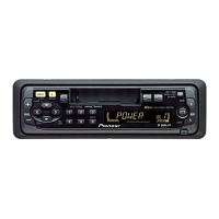
Pioneer KEH-P2033XM Specifications

General IconGeneral
TypeCar Receiver
CD PlayerYes
EqualizerYes
Display TypeLCD
BluetoothNo
Channels4
FM TunerYes
AM TunerYes
Detachable FaceYes
Tuner TypeAM/FM
DIN Size1-DIN
Faceplate SecurityDetachable Faceplate
Output Power22 Watts RMS per channel
CD MechanismSingle CD
Presets18 FM, 6 AM

Summary

Safety Information

1. Specifications

Key Specifications Overview

Details general, audio, cassette player, and FM tuner specifications including power, dimensions, frequency response, and sensitivity.

2. Exploded Views and Parts List

2.1 Packing and Contents

Lists and illustrates the packaging components and accessories included with the product.

2.2 Exterior Components

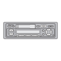
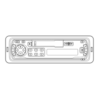
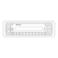
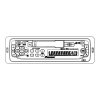
Details and illustrates the external parts and their assembly for the product.

2.3 Cassette Mechanism Components

Provides an exploded view and parts list for the cassette mechanism assembly.

3. Block Diagram and Schematic Diagram

3.1 Block Diagram

Presents the overall block diagram illustrating the main functional units and their interconnections.

3.2 Overall Connection Diagram

Shows the comprehensive connection diagram of all internal units and external interfaces.

3.3 Keyboard Unit Diagram

Illustrates the block diagram for the keyboard unit, detailing its interface with the main system.

3.4 Cassette Mechanism Diagram

Presents the schematic diagram for the cassette mechanism, showing its electrical connections and components.

4. PCB Connection Diagram

4.1 Tuner Amp Unit PCB Layout

Shows the PCB layout and component placement for the Tuner Amplifier unit.

4.2 Keyboard Unit PCB Layout

Illustrates the PCB layout and component placement for the Keyboard unit.

4.3 Cassette Mechanism PCB Layout

Depicts the PCB layout and component placement for the Cassette Mechanism.

5. Electrical Parts List

Component Parts Listing

Comprehensive list of all electrical components, including resistors, capacitors, ICs, and transistors with their part numbers.

6. Adjustment

Adjustment Procedures

This chapter contains no specific adjustment information.

7. General Information

7.1 Diagnosis

Covers product diagnosis, including disassembly steps, connector functions, and troubleshooting.

7.2 Parts

Lists and describes various parts of the unit, including ICs and displays.

7.3 Operational Flow Chart

Details the operational sequence and flow of the device, including power-on and communication protocols.

7.4 Cleaning

Provides guidelines for cleaning essential components like cassette heads and pinch rollers.

8. Operations

Key Controls and Functions

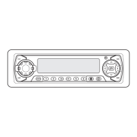
Details the function of each button on the head unit, including source selection, tuning, and playback controls.

Related product manuals