EasyManua.ls Logo

Pioneer KEH-P5850 X1M/ES User Manual

Pioneer KEH-P5850 X1M/ES
55 pages
To Next Page IconTo Next Page
Page #1 background imageLoading...
Page #1 background image
PIONEER ELECTRONIC CORPORATION 4-1, Meguro 1-Chome, Meguro-ku, Tokyo 153-8654, Japan
PIONEER ELECTRONICS SERVICE INC. P.O.Box 1760, Long Beach, CA 90801-1760 U.S.A.
PIONEER ELECTRONIC [EUROPE] N.V. Haven 1087 Keetberglaan 1, 9120 Melsele, Belgium
PIONEER ELECTRONICS ASIACENTRE PTE.LTD. 501 Orchard Road, #10-00, Wheelock Place, Singapore 238880
C PIONEER ELECTRONIC CORPORATION 1998
K-ZZU. OCT. 1998 Printed in Japan
ORDER NO.
CRT2259
MULTI-CD CONTROL HIGH POWER CASSETTE PLAYER WITH FM/AM TUNER
KEH-P580 X1M/UC
Service
Manual
CONTENTS
1. SAFETY INFORMATION............................................2
2. EXPLODED VIEWS AND PARTS LIST ......................2
3. SCHEMATIC DIAGRAM.............................................8
4. PCB CONNECTION DIAGRAM................................22
5. ELECTRICAL PARTS LIST........................................32
6. ADJUSTMENT.........................................................41
7. GENERAL INFORMATION.......................................43
7.1 PARTS................................................................43
7.1.1 IC...............................................................43
7.1.2 DISPLAY ...................................................47
7.2DISASSEMBLY ...................................................48
7.3BLOCK DIAGRAM ..............................................49
8. OPERATIONS AND SPECIFICATIONS....................50
NOTE:
- See the separate manual CX-631(CRT1640) for the cassette mechanism description.
- The cassette mechanism assy employed in this model is one of 2L series.
- Dolby noise reduction manufactured under license from Dolby Laboratories Licensing Corporation.
"Dolby" and the double-D symbol are trademarks of Dolby Laboratories Licensing Corporation.
- This service manual does not describe the CD test mode.
For the operations in the CD test mode, refer to the CD player's Service Manual.
KEH-P5850 X1M/ES
KEH-P5800 X1M/UC
KEH-P5850/X1M/ES
Question and Answer IconNeed help?

Do you have a question about the Pioneer KEH-P5850 X1M/ES and is the answer not in the manual?

Pioneer KEH-P5850 X1M/ES Specifications

General IconGeneral
CategoryCar Receiver
ModelKEH-P5850 X1M/ES
BrandPioneer
MP3 PlaybackNo
USB PortNo
BluetoothNo
Display TypeLCD
Detachable FaceYes
Bass BoostYes
LoudnessYes
Fader ControlYes
ClockYes
DIN Size1 DIN
Max Power Output45 Watts
Power Output45W x 4
Tuner TypeFM/AM

Summary

SAFETY INFORMATION

GENERAL SAFETY INFORMATION

General safety precautions for qualified service technicians, including warnings about unqualified repairs and lead in solder.

EXPLODED VIEWS AND PARTS LIST

PACKING SECTION PARTS LIST

Lists parts for product packing and assembly, noting unavailable items.

SCHEMATIC DIAGRAM

OVERALL CONNECTION DIAGRAM

Provides a general overview of electrical connections, with notes on component symbols.

TUNER AMP UNIT SCHEMATIC

Detailed schematic diagram for the Tuner Amplifier Unit, showing component connections.

POWER AMP SCHEMATIC

Detailed schematic diagram for the Power Amplifier section.

FM/AM TUNER UNIT SCHEMATIC

Schematic diagram for the FM/AM Tuner Unit, including front end and oscillator circuits.

KEYBOARD UNIT SCHEMATIC

Schematic diagram illustrating the connections for the Keyboard Unit.

CASSETTE MECHANISM MODULE SCHEMATIC

Schematic diagram for the Cassette Mechanism Module, detailing the Deck Unit.

PCB CONNECTION DIAGRAM

TUNER AMP UNIT PCB DIAGRAM

PCB connection diagram for the Tuner Amplifier Unit, showing component placement.

FM/AM TUNER UNIT PCB DIAGRAM

PCB connection diagram for the FM/AM Tuner Unit.

KEYBOARD UNIT PCB DIAGRAM

PCB connection diagram for the Keyboard Unit.

CASSETTE MECHANISM MODULE PCB DIAGRAM

PCB connection diagram for the Cassette Mechanism Module.

ELECTRICAL PARTS LIST

MISCELLANEOUS AND RESISTORS PARTS

Lists miscellaneous components (ICs, transistors) and resistors with part numbers.

CAPACITORS PARTS

Lists capacitors with their respective part numbers and specifications.

ADJUSTMENT PROCEDURES

Connection Diagram

Diagram showing connections for adjustment procedures, including test equipment.

FM AND DOLBY B NR ADJUSTMENTS

Adjustment steps for FM tuner (UC & ES models) and Dolby B NR.

GENERAL INFORMATION

PARTS AND IC LISTINGS

Lists general parts and integrated circuits (ICs) used in the unit.

PIN FUNCTIONS

Explains the function of each pin for key ICs like PD4973A and PD6278A.

DISPLAY WIRING

DISASSEMBLY INSTRUCTIONS

COMPONENT REMOVAL STEPS

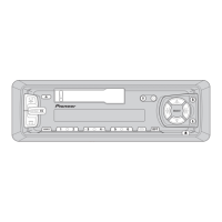
Detailed steps for removing the case, panel unit, and tuner amp unit.

SYSTEM BLOCK DIAGRAM

OPERATIONS GUIDE

HEAD UNIT OPERATION

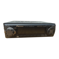
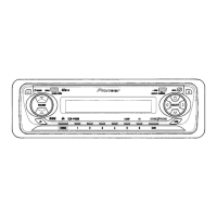
Key operations including source selection, volume adjustment, and turning the unit off.

TUNER OPERATION

TUNING METHODS AND PRESETS

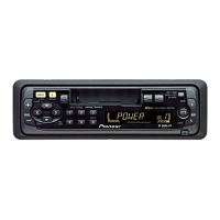
Describes manual/seek tuning and how to memorize/recall broadcast stations.

CASSETTE PLAYER OPERATION

TAPE CONTROL FEATURES

Explains fast forward, rewind, music search, and tape type indicators.

MULTI-CD PLAYER OPERATION

PLAYER AND TRACK NAVIGATION

How to switch players and navigate tracks on a CD.

DISC SELECTION AND TITLES

Methods for selecting discs and displaying CD titles.

CD PLAYER OPERATION (ONE DISC)

TRACK NAVIGATION AND TITLES

How to navigate tracks and display CD titles on a single CD player.

TECHNICAL SPECIFICATIONS

GENERAL, AMPLIFIER, AND TUNER SPECS

Technical specs for general, amplifier, FM, and AM tuner sections.

CASSETTE PLAYER SPECS

Technical specifications for the cassette player, including tape speed and frequency response.

Related product manuals