Do you have a question about the Pioneer KEH-P5200RDS and is the answer not in the manual?
Details on connecting the car stereo, power amp, and other components.
How to use the clear button to reset the microprocessor.
Instructions on how to turn the unit on and select sources.
Guide to adjusting volume, balance, fader, bass, treble, and F.I.E. function.
Instructions for tuning, band selection, and manual tuning.
Adjusting seek sensitivity and using RDS features like PS, AF, TP/TA.
Utilizing PTY Display, PTY Seek, and PTY Alarm features.
Using AF function for continuous reception and REG ON/OFF mode.
Explanation of PTY indication switching and setting program types.
Using TP/EON-TP, TA reception, and basic tape deck operations.
Using Dolby NR, Tape Selector, Fast Forward/Rewind, and FLEX.
Dolby NR, Tape Selector, Fast Forward/Rewind, and CD player usage precautions.
Instructions and precautions for operating the multi-play CD player.
Track search, Repeat modes, Random Play, and ITS programming.
Erasing ITS programs and inputting disc titles.
Using COMP (Compression) and D.B.E. (Dynamic Bass Emphasis) functions.
Entering and exiting test mode for IP BUS type CD multi-players.
Connection diagram for the FM/AM tuner unit.
Adjusting AM/FM signals using SSG, mV Meter, and DC V Meter.
Adjusting RDS signals and Dolby NR using test tape.
Steps to remove the case, cassette mechanism, front grille, and chassis unit.
Explanation of error code display and a list of common error codes.
How to enter and use the new test mode for CD player analysis.
Key relations in test modes and detailed error codes with causes.
Status codes indicating operation progress and examples of display.
Parts list detailing miscellaneous components, resistors, and capacitors.
Continuation of electrical parts list for capacitors and resistors.
Parts lists for specific units (Dolby NR AMST, Key Board) and miscellaneous items.
Electrical parts list for capacitors, resistors, and the FM/AM Tuner Unit.
Miscellaneous parts list for the Key Board Unit.
Comparison of Tuner Amp Unit part numbers across different models.
Parts list comparison for Tuner Amp Unit and Key Board Unit across models.
Pin diagram and functions for IC PA2022B.
Pin diagram and functions for IC SN761025DL.
Pin diagram and functions for IC LC72146M.
Pin diagram and functions for IC PAL003A.
Detailed pin functions and operations for PDR017A.
Continuation of detailed pin functions and operations for PDR017A.
Pin diagram and functions for IC PA0059AM.
Block diagram and pin functions for PMR001B.
Segment and common pin assignments for the LCD display.
Overall block diagram of the KEH-P5200RDS/EW unit.
Block diagram for multiple models, detailing interconnected units.
Block diagram illustrating signal flow and component connections.
Circuit diagram and component layout for the Tuner Amp Unit.
Circuit diagrams for Cassette Mechanism, Tuner, Dolby NR, and IP BUS units.
Circuit diagram for the Key Board Unit.
Circuit diagram for the FM/AM Tuner Unit, showing component details.
Circuit diagrams for Cassette Mechanism and EQ Amplifier sections.
Circuit diagram for the Key Board Unit.
Circuit diagrams detailing connections for IC451, Isolator, and IP Bus Driver.
Circuit diagram related to illumination switching.
Circuit diagram for the Tuner Amp Unit for specific models.
Circuit diagram for the Tuner Amp Unit, detailing component connections.
Circuit diagram for the Tuner Amp Unit for specific models.
Circuit diagram for the Tuner Amp Unit, detailing component connections.
Circuit diagrams for Cassette Mechanism, EQ Amp, and Key Board Unit.
Circuit diagrams for IC451, Isolator, and IP Bus Driver.
Circuit diagram related to illumination switching.
Circuit diagram for the Tuner Amp Unit for specific models.
Circuit diagram for the Tuner Amp Unit, detailing component connections.
Circuit diagrams for Cassette Mechanism, EQ Amp, and Key Board Unit.
Circuit diagram connections for IC451.
Circuit diagram related to illumination switching.
Connection diagram for the Tuner Amp Unit.
Connection diagram for the Tuner Amp Unit for specific models.
Circuit diagram for the Tuner Amp Unit for specific models.
Circuit diagram for the Tuner Amp Unit, detailing component connections.
Circuit diagram for the FM/AM Tuner Unit.
Circuit diagram for the FM/AM Tuner Unit, showing component details.
Circuit diagram related to FM Multiplex and PNS processing.
Component layout diagram for the Tuner Unit.
Component layout diagram for the Tuner Amp Unit.
Circuit diagram for the Key Board Unit.
Diagram showing connections to the Key Board Unit.
Pin assignments for the LCD display driver IC.
Pin diagram and functions for the LCD driver IC.
Component layout diagram for the Tuner Amp Unit.
Circuit and connection diagrams for the Dolby NR AMST Unit.
Circuit and connection diagrams for the Cassette Mechanism Assembly.
List of miscellaneous parts including ICs, transistors, inductors, and heat sinks.
Electrical parts list for resistors and capacitors.
Parts list for mechanical components like screws, springs, holders, and chassis parts.
Comparison of part numbers across different models for key components.
List of parts for the Cassette Mechanism Assembly.
Continuation of the parts list for the Cassette Mechanism Assembly.
List of parts included in the Accessory Assy.
List of non-spare parts included in the packing.
Details on Owner's Manual part numbers and available languages.
Comparison of parts lists across different models for key items.
| Type | Car Receiver |
|---|---|
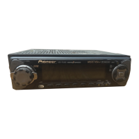
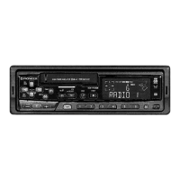
| Brand | Pioneer |
| Model | KEH-P5200RDS |
| Radio Tuner | FM/AM |
| RDS | Yes |
| Output Power | 4 x 50W |
| CD Playback | Yes |
| MP3 Playback | Yes |
| USB Port | No |
| Aux Input | No |
| Display Type | LCD |
| Equalizer | Yes |
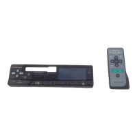
| Remote Control | Optional |
| Dimensions | 178 x 50 x 160 mm |
| Form Factor | 1 DIN |
| Media Type | CD, MP3 |