EasyManua.ls Logo

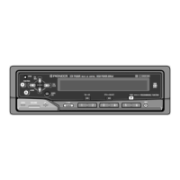
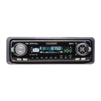
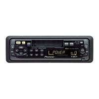
Pioneer KEH-P6950 User Manual

Pioneer KEH-P6950
50 pages
To Next Page IconTo Next Page
Page #1 background imageLoading...
Page #1 background image
PIONEER CORPORATION 4-1, Meguro 1-Chome, Meguro-ku, Tokyo 153-8654, Japan
PIONEER ELECTRONICS SERVICE INC. P.O.Box 1760, Long Beach, CA 90801-1760 U.S.A.
PIONEER ELECTRONIC [EUROPE] N.V. Haven 1087 Keetberglaan 1, 9120 Melsele, Belgium
PIONEER ELECTRONICS ASIACENTRE PTE.LTD. 253 Alexandra Road, #04-01, Singapore 159936
C PIONEER CORPORATION 1999
K-ZZS. NOV. 1999 Printed in Japan
ORDER NO.
CRT2430
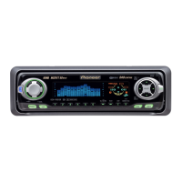
MULTI-CD CONTROL HIGH POWER CASSETTE PLAYER WITH FM/AM TUNER
KEH-P690 X1N/UC
Service
Manual
KEH-P690/X1N/UC
- This service manual should be used together with the following manual(s):
Model No. Order No. Mech. Module Remarks
CX-1011 CRT2406 3L Cassette Mech. Module:Mech.Description, Disassembly, Adjustment
KEH-P6950 X1N/ES
NOTE:
- Dolby noise reduction manufactured under license from Dolby Laboratories Licensing Corporation.
"Dolby" and the double-D symbol are trademarks of Dolby Laboratories Licensing Corporation.
CONTENTS
1. SAFETY INFORMATION ............................................2
2. EXPLODED VIEWS AND PARTS LIST.......................2
3. BLOCK DIAGRAM AND SCHEMATIC DIAGRAM .....9
4. PCB CONNECTION DIAGRAM ................................20
5. ELECTRICAL PARTS LIST ........................................30
6. ADJUSTMENT..........................................................36
7. GENERAL INFORMATION .......................................37
7.1 DIAGNOSIS ........................................................37
7.1.1 TEST MODE..............................................37
7.1.2 DISASSEMBLY .........................................40
7.2 PARTS .................................................................41
7.2.1 IC................................................................41
7.2.2 DISPLAY....................................................44
8. OPERATIONS AND SPECIFICATIONS.....................45
w
w
w
.
x
i
a
o
y
u
1
6
3
.
c
o
m
Q
Q
3
7
6
3
1
5
1
5
0
9
9
2
8
9
4
2
9
8
T
E
L
1
3
9
4
2
2
9
6
5
1
3
9
9
2
8
9
4
2
9
8
0
5
1
5
1
3
6
7
3
Q
Q
TEL 13942296513 QQ 376315150 892498299
http://www.xiaoyu163.com
Question and Answer IconNeed help?

Do you have a question about the Pioneer KEH-P6950 and is the answer not in the manual?

Pioneer KEH-P6950 Specifications

General IconGeneral
TypeCar Receiver
DIN Size1 DIN
Channels4
TunerAM/FM
CD PlaybackYes
MP3 PlaybackYes
USB PortNo
BluetoothNo
EqualizerYes
Display TypeLCD
Preamp OutputsYes
Detachable FaceYes
CD-R/RW CompatibilityYes
WMA PlaybackYes
AUX InputYes
CD Changer ControlYes
Max Power Output50W x 4
RMS Power Output22 Watts x 4
Anti-Theft ProtectionYes, Detachable Face
EQ3-Band
Preamp Outputs (Details)Front/Rear
Frequency Response5 - 20000 Hz
Dimensions178mm x 50mm x 160mm

Summary

SAFETY INFORMATION

EXPLODED VIEWS AND PARTS LIST

2.3 CASSETTE MECHANISM MODULE

Detailed diagram and parts list for the cassette mechanism.

BLOCK DIAGRAM AND SCHEMATIC DIAGRAM

3.1 BLOCK DIAGRAM

Provides an overview of the product's functional blocks and their interconnections.

3.2 OVERALL CONNECTION DIAGRAM(GUIDE PAGE)

Illustrates how various units connect to each other.

3.3 FM/AM TUNER UNIT

Detailed schematic diagram of the FM/AM Tuner Unit.

3.4 CASSETTE MECHANISM MODULE

Schematic diagram for the cassette mechanism module.

PCB CONNECTION DIAGRAM

4.1 TUNER AMP UNIT

Illustrates the component placement and connections on the Tuner Amplifier PCB.

4.2 FM/AM TUNER UNIT

PCB layout and connections for the FM/AM Tuner Unit.

4.3 KEYBOARD UNIT

PCB layout and connections for the Keyboard Unit.

4.4 DECK UNIT,REEL SENSE PCB,PANEL PCB UNIT

PCB layouts for Deck, Reel Sense, and Panel units.

D DECK UNIT

PCB layout and connections for the Deck Unit.

ELECTRICAL PARTS LIST

ADJUSTMENT

GENERAL INFORMATION

7.1 DIAGNOSIS

Information on diagnosing issues and understanding product behavior.

7.1.1 TEST MODE

Detailed steps and key combinations to enter the product's test mode.

Error Cause (Error Number) Code

Lists error codes, classifications, descriptions, and their causes for troubleshooting.

7.1.2 DISASSEMBLY

Step-by-step guide for disassembling the unit.

PARTS

7.2.1 IC

Lists pin functions and operations for integrated circuits (ICs).

7.2.2 DISPLAY

Diagram and pin assignments for the display unit.
Connecting the Units

Related product manuals