EasyManua.ls Logo

Pioneer KEH-P9700REW User Manual

Pioneer KEH-P9700REW
58 pages
To Next Page IconTo Next Page
Page #1 background imageLoading...
Page #1 background image
PIONEER ELECTRONIC CORPORATION 4-1, Meguro 1-Chome, Meguro-ku, Tokyo 153-8654, Japan
PIONEER ELECTRONICS SERVICE INC. P.O.Box 1760, Long Beach, CA 90801-1760 U.S.A.
PIONEER ELECTRONIC [EUROPE] N.V. Haven 1087 Keetberglaan 1, 9120 Melsele, Belgium
PIONEER ELECTRONICS ASIACENTRE PTE.LTD. 501 Orchard Road, #10-00, Wheelock Place, Singapore 238880
C PIONEER ELECTRONIC CORPORATION 1998
K-ZEU MAY 1998 Printed in Japan
ORDER NO.
CRT2197
MULTI-CD/MD/DAB CONTROL DSP HIGH POWER CASSETTE PLAYER WITH RDS TUNER
Se
r
v
i
c
e
M
a
nu
a
l
KEH-P9700R EW
NOTE:
- See the separate manual CX-631(CRT1640) for the cassette mechanism description.
- The cassette mechanism assy employed in this model is one of 2L series
- Dolby noise reduction manufactured under license from Dolby Laboratories Licensing Corporation.
"Dolby" and the double-D symbol are trademarks of Dolby Laboratories Licensing Corporation.
- This service manual does not describe the CD test mode.
For the operations in the CD test mode, refer to the CD player's Service Manual.
KEH-P9750 ES
CONTENTS
1. SAFETY INFORMATION............................................2
2. EXPLODED VIEWS AND PARTS LIST ......................2
3. SCHEMATIC DIAGRAM...........................................10
4. PCB CONNECTION DIAGRAM................................31
5. ELECTRICAL PARTS LIST........................................45
6. ADJUSTMENT.........................................................58
7. GENERAL INFORMATION.......................................60
7.1PARTS .................................................................60
7.1.1 IC...............................................................60
7.1.2 DISPLAY ...................................................70
7.2DIAGNOSIS ........................................................71
7.2.1 DISASSEMBLY.........................................71
7.3EXPLANATION ...................................................72
7.3.1 BLOCK DIAGRAM....................................72
8. OPERATIONS AND SPECIFICATIONS....................74
KEH-P9750/ES
MULTI-CD CONTROL DSP HIGH POWER CASSETTE PLAYER WITH FM/AM TUNER
Question and Answer IconNeed help?

Do you have a question about the Pioneer KEH-P9700REW and is the answer not in the manual?

Pioneer KEH-P9700REW Specifications

Power IconPower
power source voltage14.4 V DC
max current consumption10 A
load impedance4 Ω (4 – 8 Ω allowable)
FM Tuner IconFM Tuner
frequency range87.5 – 108 MHz
usable sensitivity11 dBf (1.0 µV/75 Ω, mono, S/N: 30 dB)
signal-to-noise ratio70 dB (IEC-A network)
distortion0.3% (at 65 dBf, 1 kHz, stereo)
frequency response30 – 15, 000 Hz (±3 dB)
stereo separation40 dB (at 65 dBf, 1 kHz)
Amplifier (KEH-P9700R/EW) IconAmplifier (KEH-P9700R/EW)
maximum power output40 W × 4
continuous power output25 W × 4 (DIN45324, +B =14.4 V)
preout output level/output impedance500 mV/1 kΩ
Amplifier (KEH-P9750/ES) IconAmplifier (KEH-P9750/ES)
maximum power output40 W × 4
continuous power output20 W per channel min. into 4 ohms
preout output level/output impedance500 mV/1 kΩ
AM Tuner (KEH-P9750/ES) IconAM Tuner (KEH-P9750/ES)
frequency range531 – 1, 602 kHz (9 kHz)
usable sensitivity18 µV (S/N: 20 dB)
selectivity50 dB (±9 kHz)
DSP IconDSP
equalizer frequency50, 80, 125, 200, 315, 500, 800, 1.25 k, 2 k, 3.15 k, 5 k, 8 k, 12.5 k (Hz)
equalizer level± 12 dB (2 dB)
auto equalizer frequency (STD Mode)50, 80, 125, 200, 315, 500, 800, 1.25 k, 2 k, 3.15 k, 5 k, 8 k, 12.5 k (Hz)
Cassette Player IconCassette Player
tape speed4.76 cm/sec.(+0.14cm/sec., -0.05cm/sec.)
fast forward/rewinding timeApprox. 100 sec. for C-60
wow & flutter0.09% (WRMS)
Weight and Dimensions IconWeight and Dimensions
weight1.8 kg
dimensions (DIN) chassis width178 mm
dimensions (DIN) chassis height50 mm
dimensions (DIN) chassis depth155 mm
dimensions (DIN) nose width188 mm
dimensions (DIN) nose height58 mm
dimensions (DIN) nose depth20 mm

Summary

Exterior Views

Exterior Views

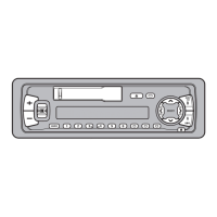
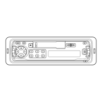
Illustrates the external components and their arrangement.

Exploded Views and Parts Lists

Main Unit Parts List

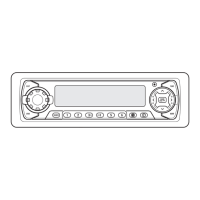
Lists all external and internal components for the main unit.

Cassette Mechanism Module

Detailed diagrams and parts list for the cassette mechanism module.

Cassette Mechanism Module Parts List

Itemized list of parts for the cassette mechanism module.

Schematic Diagrams

FM/AM Tuner Unit Schematics

Circuit diagrams for the FM/AM tuner unit.

Keyboard Unit Schematics

Circuit diagrams for the keyboard unit.

DSP Unit Schematics

Circuit diagrams for the DSP unit, parts F-b and guide page.

Microphone Jack Unit Schematics

Circuit diagrams for the microphone jack unit.

Electrical Parts Lists

Tuner Unit Electrical Parts List

List of electrical components for the FM/AM Tuner Unit.

Tuner Amp Unit Contrast Table

Compares parts between KEH-P9700R/EW and KEH-P9750/ES tuner units.

Miscellaneous Parts List

Lists miscellaneous parts for PCB Unit, Reel PCB, Switch PCB, etc.

Adjustment Procedures

FM Adjustment (EW Model)

Procedure for adjusting FM reception parameters for the EW model.

FM Adjustment (ES Model)

Procedure for adjusting FM reception parameters for the ES model.

RDS SL Adjustment

Procedure for adjusting RDS SL settings.

Dolby B NR Adjustment

Procedure for adjusting Dolby B NR settings.

General Information and Component Details

Integrated Circuits (ICs) Overview

Lists integrated circuits used in the unit and their functions.

PD4903A Pin Functions

Details the function of each pin for the PD4903A IC.

PD6237C Pin Functions

Details the function of each pin for the PD6237C IC.

SED1540FOA Pin Functions

Details the function of each pin for the SED1540FOA IC.

SED1526F0A Pin Functions

Details the function of each pin for the SED1526F0A IC.

PD5445C Pin Functions

Details the function of each pin for the PD5445C IC.

AK7712AVT Pin Functions

Details the function of each pin for the AK7712AVT IC.

Diagnosis and Disassembly

Disassembly Procedures

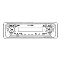
Step-by-step instructions for disassembling major unit components.

System Architecture

System Block Diagram

Visual representation of the unit's functional blocks and connections.

Specifications

Operations and Specifications (ES Model)

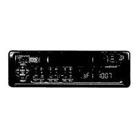
Details operational modes and technical specifications for the ES model.

Related product manuals